Radio frequency receiver based on carrier enhancement technology

A radio frequency receiver and carrier technology, applied in the direction of electrical components, transmission systems, etc., can solve the problems of post-amplification noise, increased frequency conversion loss, and increased overall noise, and achieve increased frequency conversion gain, high gain, and dispersion low effect

Active Publication Date: 2018-07-27
ZHEJIANG UNIV
View PDF4 Cites 0 Cited by
  • Summary
  • Abstract
  • Description
  • Claims
  • Application Information

AI Technical Summary

Problems solved by technology

However, when the traditional time-varying transmission line is at low frequency, the frequency conversion gain is positive. When the frequency reaches 0.6GHz, the frequency conversion gain is negative. As the frequency further increases, the frequency conversion loss increases
Although the passive network has the advantage of low noise, as far as the noise of the overall system is concerned, when the frequency conversion gain is continuously reduced or even negative, the noise of the subsequent stage is amplified, thereby increasing the overall noise
For the above problems, there is a way to feed back the received signal at the output end to the input end, but it can only achieve high gain in a narrow band

Method used


Image

  • Radio frequency receiver based on carrier enhancement technology
  • Radio frequency receiver based on carrier enhancement technology
  • Radio frequency receiver based on carrier enhancement technology

Examples


Embodiment Construction

[0025] The present invention will be further elaborated and illustrated below in conjunction with the accompanying drawings and specific embodiments. The technical features of the various implementations in the present invention can be combined accordingly on the premise that there is no conflict with each other.

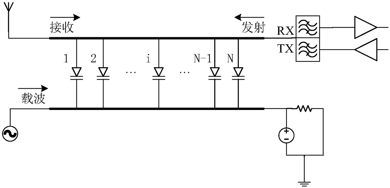
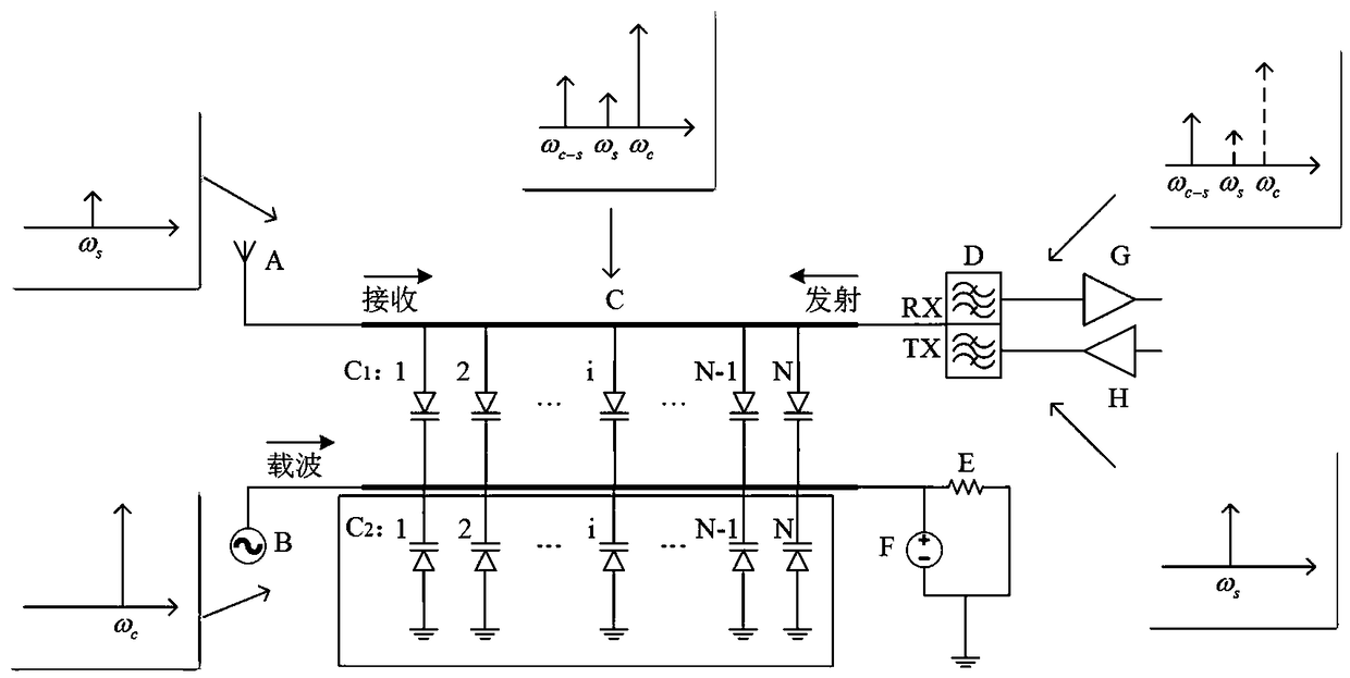
[0026] refer to figure 2 , RF receiver architecture based on carrier enhancement technology, including antenna (A), AC current source (B), time-varying transmission line (C), duplexer (D), 50Ohm load (E), low noise amplifier (G) and power amplifier (H). in:

[0027] Antenna (A), used for receiving and transmitting signals of the same frequency;

[0028] An alternating current source (B) for outputting a carrier signal;

[0029] A time-varying transmission line (C), including an upper transmission line, a lower transmission line and two sets of varactor diodes, the upper transmission line is used to propagate receiving signals and transmitting signals, and the l...


PUM


Abstract

The invention discloses a radio frequency receiver based on a carrier enhancement technology, and belongs to the technical field of electronic circuits. The radio frequency receiver comprises an antenna, an alternating current source, a time-varying transmission line, a duplexer, a 50-Ohm load, a direct current bias, a low-noise amplifier and a power amplifier, wherein an upper transmission line of the time-varying transmission line is used for transmitting a receiving signal and an emitting signal; a lower transmission line of the time-varying transmission line transmits a carrier wave; the two transmission lines are connected in parallel with an abrupt junction variable capacitance diode group in an equal spacing manner to perform frequency mixing on the carrier wave and the receiving signal; the lower transmission line and the ground are connected in parallel with an MOS (Metal Oxide Semiconductor) variable capacitance diode group in an equal spacing manner to increase an amplitudevalue of the carrier wave. The radio frequency receiver based on the carrier enhancement technology, which is disclosed by the invention, can realize a high gain within a relatively wide frequency band of the receiving signal, solves the problem of loss caused after a conventional time-varying transmission line enters a high frequency, reduces a requirement of a backward-stage duplexer, and in addition, reduces backward-stage noise, thereby improving the overall noise of a system.

Description

technical field [0001] The invention belongs to the technical field of electronic circuits, and more specifically relates to a radio frequency receiver based on a carrier strengthening technology. Background technique [0002] The high isolation and low noise of the time-varying transmission line using the distributed modulation capacitor (DMC) structure shows the potential advantages of being applied in the front end of a full-duplex transceiver. In a time-varying transmission line, the antenna receives and transmits signals at the same frequency but in different directions of propagation. The signal received from the antenna is modulated by the carrier during transmission to the transmitter because the propagation direction is in the same direction as the carrier; while the transmitted signal is directly transmitted to the antenna because the propagation direction is reversed, causing only little interference to the DMC. The varactor diodes connected in parallel at equal ...

Claims


Application Information

Patent Timeline
Patent Type & Authority Applications(China)
IPC IPC(8): H04B1/12H04B1/16
CPCH04B1/123H04B1/16
Inventor 李昀诗虞小鹏
Owner ZHEJIANG UNIV
Why Eureka
Try Eureka