Supercharge Your Innovation With Domain-Expert AI Agents!

DCM detection system based on CAN network

A detection system and network technology, applied in the detection field, can solve problems such as low detection accuracy and complex detection methods of door controllers, and achieve the effects of high detection efficiency, high detection accuracy, and simple detection methods

Pending Publication Date: 2021-04-02
AEROSPACE HI TECH HLDG GROUP
View PDF0 Cites 0 Cited by
  • Summary
  • Abstract
  • Description
  • Claims
  • Application Information

AI Technical Summary

Problems solved by technology

[0003] The present invention aims to solve the problems of complex detection methods and low detection accuracy in the existing detection of car door controllers

Method used


Image

  • DCM detection system based on CAN network
  • DCM detection system based on CAN network

Examples


specific Embodiment approach 1

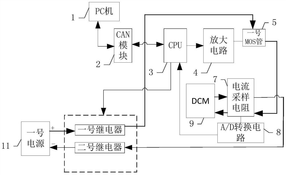
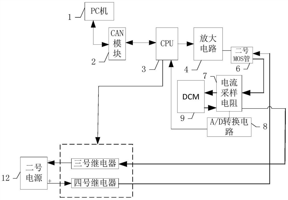
[0026] Specific implementation mode one: refer to figure 1 and figure 2 Describe this embodiment in detail, the DCM detection system based on CAN network described in this embodiment, described system comprises PC machine 1, CAN module 2, CPU3, amplifying circuit 4, No. 1 MOS tube 5, No. 2 MOS tube 6, Current sampling resistor 7, A / D conversion circuit 8, four relays, No. 1 power supply 11 and No. 2 power supply 12,

[0027] The four relays include No. 1 relay, No. 2 relay, No. 3 relay and No. 4 relay;

[0028] PC 1, used to send a forward current detection command or a reverse current detection command;

[0029] CPU3 is connected to PC 1 through CAN module 2;

[0030] The CPU3 is used to receive the forward current detection command or the reverse current detection command sent by the PC 1 through the CAN module 2, and generate a PWM forward drive signal according to the forward current detection command or generate a PWM reverse current detection command according to the...

specific Embodiment approach 2

[0039]Embodiment 2: This embodiment is a further description of the CAN network-based DCM detection system described in Embodiment 1. In this embodiment, the current sampling resistor 7 is a 12-bit A / D processing module.

specific Embodiment approach 3

[0040] Specific embodiment three: This embodiment is a further description of the CAN network-based DCM detection system described in specific embodiment one. In this embodiment, the forward current value is 3.5A, and the preset current range is 3.5A±10 %.


PUM


Abstract

The invention discloses a DCM detection system based on a CAN network, and relates to the field of detection. The invention aims to solve the problems of complex mode and low detection precision of the existing vehicle door controller detection method. A positive detection command or a negative detection command is sent out, the positive detection command applies a positive voltage sent by a firstpower supply to a DCM through a CPU, a first MOS tube and a current sampling resistor, and the negative detection command applies the positive voltage sent by the first power supply to the DCM through the CPU, a second MOS tube and the current sampling resistor. An A / D conversion circuit can detect forward voltage values at the two ends of the current sampling resistor, calculate a forward current value passing through the DCM according to the forward voltage values and the resistance value of the current sampling resistor, and compare the forward current value with a preset current range inthe CPU to detect whether the DCM is qualified or not. The system is used to detect DCM.

Description

technical field [0001] The invention relates to a detection system for DCM and belongs to the field of detection. Background technique [0002] DCM is a door controller, which is an electronic product, so before leaving the factory, it is necessary to check whether the DCM is qualified. The existing detection method only simulates the motor with resistance, applies a signal to the door controller, makes the door controller control the motor simulated with resistance, and artificially checks the movement of the motor simulated with resistance. This artificial detection method uses resistance to simulate the motor. , making the detection method complex. In addition, this method will use the motor simulated by the resistance to generate a counter electromotive force and apply it to the door controller in reverse, causing damage to the door controller. Therefore, the existing detection method is complicated and the detection accuracy is low. Contents of the invention [0003]...

Claims


Application Information

Patent Timeline
IPC IPC(8): G05B23/02
CPCG05B23/0213
Inventor 刘雨胡伟刘金泽高伟杨茜刘培才王洋
Owner AEROSPACE HI TECH HLDG GROUP
Features
  • R&D
  • Intellectual Property
  • Life Sciences
  • Materials
  • Tech Scout
  • Unparalleled Data Quality
  • Higher Quality Content
  • 60% Fewer Hallucinations
Learn More