
Optical satellite rapid fusion product manufacturing method based on target area

A technology for optical satellites and target areas, which is applied in the field of optical satellite rapid fusion product production solutions, can solve the problems of data organization redundancy, affecting the timeliness of high-resolution satellites, and poor flexibility of processing models, etc.

Active Publication Date: 2021-04-02
HUBEI UNIV OF TECH
View PDF4 Cites 6 Cited by
  • Summary
  • Abstract
  • Description
  • Claims
  • Application Information

AI Technical Summary

Problems solved by technology

With the continuous improvement of satellite spatial resolution, the data volume of standard scene products can usually reach tens of GB, and the fusion products under the condition of large side swing and large pitch can even reach hundreds of GB, which is affected by computing resources, storage device IO, network bandwidth, The limitations of terminal stand-alone performance and the problems caused by excessive data volume have become increasingly prominent. It takes several hours to place an order for a standard scene product, produce a standard scene fusion product, and cut out the target area of ​​interest, which has seriously affected Timeliness of daily application and support of high-resolution satellites
Therefore, it is necessary to study the rapid production method of fusion products based on the target area to improve the information acquisition for emergency tasks in view of the data organization redundancy in the core processing link of the target fusion product in the existing ground processing system and the poor flexibility of the processing model. efficiency

Method used


Image

  • Optical satellite rapid fusion product manufacturing method based on target area
  • Optical satellite rapid fusion product manufacturing method based on target area
  • Optical satellite rapid fusion product manufacturing method based on target area

Examples


Embodiment Construction

[0061] The technical solutions in the embodiments of the present invention will be clearly and completely described below in conjunction with the accompanying drawings in the embodiments of the present invention.

[0062] A method for producing optical satellite rapid fusion products based on a target area, comprising the following steps:

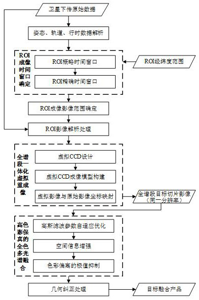
[0063] Step 1: Analyze the auxiliary data in the original data downloaded by the optical satellite, including imaging time data, attitude data, and orbit data, and provide geometric parameters for the rapid processing of ROI target fusion products.

[0064] Step 2, determine the ROI imaging time window. For optical linear array push-broom imaging, as long as the imaging time is determined, the attitude data and orbit data range can be determined, and the imaging line range can also be obtained at the same time. Adopt a kind of dynamic search mode to determine imaging time window, comprise the following steps in the embodiment:

[0065] 2....


PUM


Abstract

The invention discloses an optical satellite rapid fusion product manufacturing method based on a target area. The method comprises the following steps: firstly, determining an imaging time window ofa target region of interest (ROI) by adopting a dynamic search mode; projecting longitude and latitude coordinates of four corners of the ROI reversely to each CCD image, so that an ROI imaging imagerange is determined; then, carrying out image analysis processing on an original data range corresponding to the ROI, carrying out full-spectrum integrated virtual reimaging processing on ROI originalfull-color and multispectral images, and outputting a fusion-oriented full-color multispectral same-resolution image product; carrying out fusion processing on the ROI full-color multispectrum by adopting a full-color multispectrum fusion technology with high color fidelity; and finally, performing indirect geometric correction processing on the ROI fusion image to generate a target fusion product with geographic coordinates. The invention has the advantages of being small in data size, small in calculation amount and rapid in task response, and the information acquisition efficiency for theemergency task is improved.

Description

technical field [0001] The invention belongs to the field of remote sensing satellite image processing, and relates to a production scheme of optical satellite rapid fusion products based on a target area. Background technique [0002] In recent years, remote sensing earth observation technology has developed rapidly, and has entered a new era of diversification of data acquisition methods and massive information. The major project of my country's high-resolution earth observation system has been fully launched. By 2020, my country will newly develop dozens of high-resolution remote sensing satellites, realize 30 to 50 remote sensing satellites working in orbit at the same time, and conservatively estimate the data obtained every day The volume will reach hundreds of terabytes. In order to continuously improve the application efficiency of remote sensing satellites, high-resolution, wide-coverage, and multi-spectral imaging is one of the main goals for the development of rem...

Claims


Application Information

Patent Timeline
IPC IPC(8): G06T5/50G06T5/40G06T7/73G01J3/28
CPCG06T5/50G06T5/40G06T7/75G01J3/2823G01J2003/2826G06T2207/10036G06T2207/10041
Inventor 常学立张致齐叶志伟林向阳郭鑫轶黄晓宇
Owner HUBEI UNIV OF TECH
Learn More