Secondary voltage loop automatic switching system and automatic switching method

A secondary voltage and automatic switching technology, which is applied to the integration of power network operating systems, circuit devices, and measurement of current/voltage. Fast switching action, simple and clear circuit design

Active Publication Date: 2021-04-02
XIAN RAILWAY BUREAU SCI & TECH INST
View PDF6 Cites 1 Cited by
  • Summary
  • Abstract
  • Description
  • Claims
  • Application Information

AI Technical Summary

Problems solved by technology

[0004] However, the existing circuit has the following problems: Although the existing device can meet the needs of busbar detection, it needs to switch manually after the abnormal result is detected, and the manual Switching will cause problems such as slow switching response, long switching time, operational errors, high work intensity and large personnel input

Method used


Image

  • Secondary voltage loop automatic switching system and automatic switching method
  • Secondary voltage loop automatic switching system and automatic switching method
  • Secondary voltage loop automatic switching system and automatic switching method

Examples


Embodiment 1

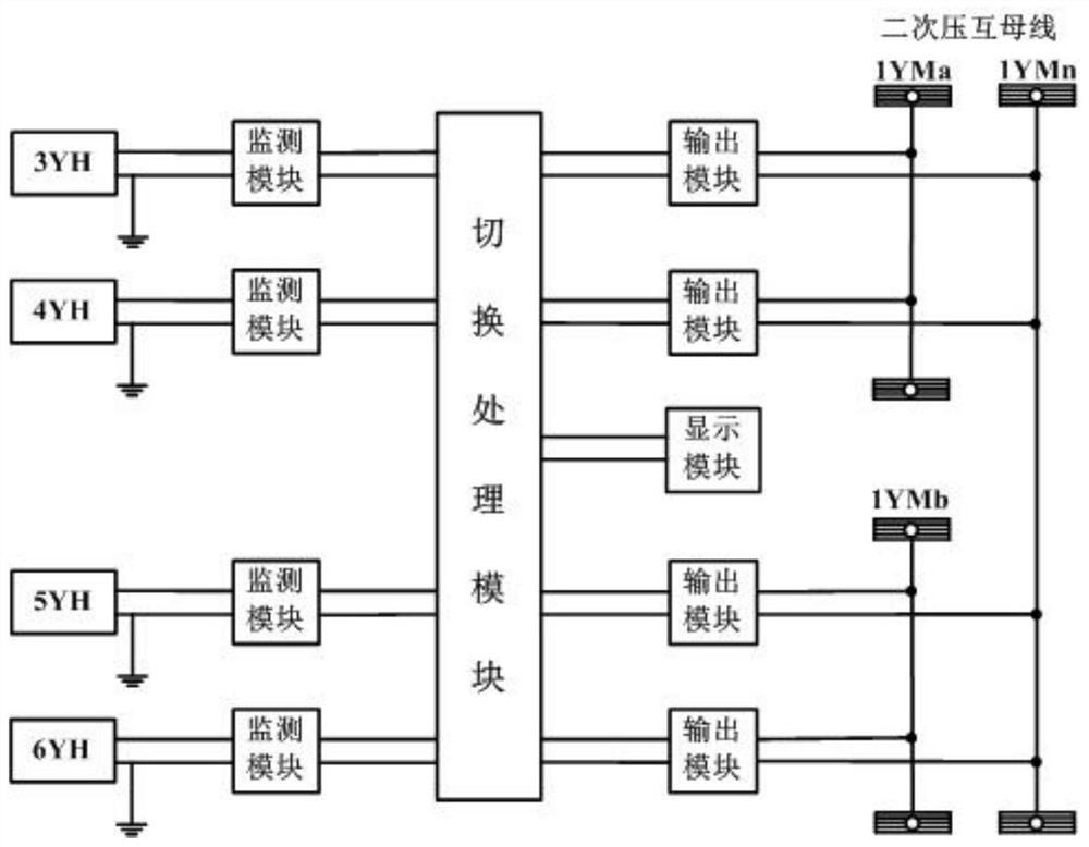
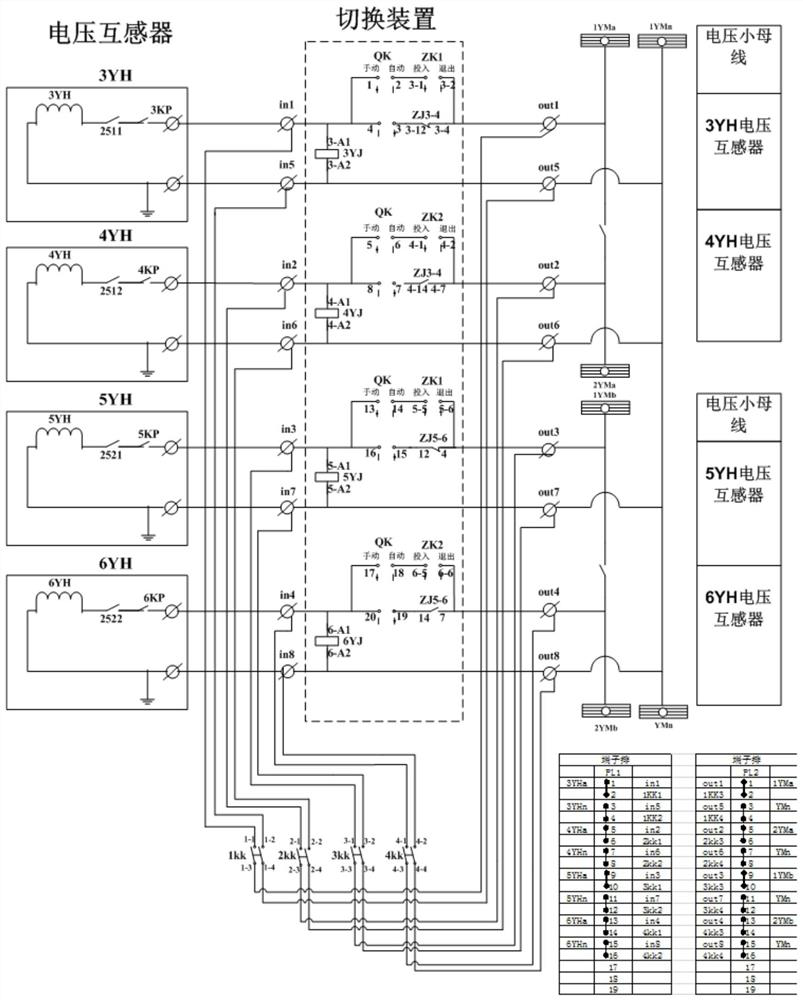
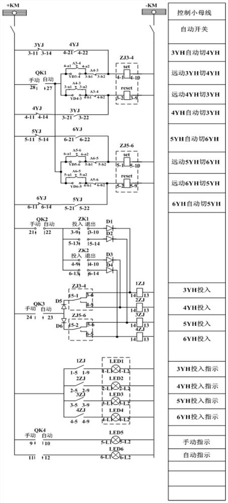
[0045] see Figure 1~3 , this embodiment is described by taking the automatic switching of the secondary voltage circuit of the 27.5KV bus of the railway traction substation as an example.

[0046] The 27.5kV bus of railway traction substation is usually equipped with voltage transformers 3YH, 5YH, 4YH, 6YH, usually 3YH, 5YH are a group, 4YH, 6YH are a group. During operation, 3YH and 5YH work, and 4YH and 6YH are used as backup. The voltage transformer is used to obtain the 27.5kV side bus voltage and convert it into AC100V according to a certain proportion. The working voltage transformer AC100V is used for relay protection and measurement of the voltage loop. , the secondary output AC100V of the backup voltage transformer is used as a backup.

[0047] The secondary voltage loop automatic switching system of this embodiment mainly includes a voltage transformer (YH) connected to the 27.5kV bus, a bypass circuit, a monitoring module, a switching module and an output circuit....

Embodiment 2

[0059] Different from Embodiment 1 and Embodiment 2, the secondary voltage circuit automatic switching system of the present invention cancels the bypass circuit and adds a programmable logic controller (PLC). Taking the model Siemens 1214C as an example for illustration, the two voltage circuits are realized. The secondary voltage loop is switched automatically. Specifically:

[0060] The input of the voltage monitor is connected to the secondary voltage circuit, see Figure 4 , the voltage monitor of this embodiment includes a voltage monitor 3YJ, a voltage monitor 4YJ, a voltage monitor 5YJ and a voltage monitor 6YJ correspondingly connected with the voltage transformer, and the voltage monitor 3YJ, the voltage monitor 4YJ, the voltage monitor The output terminals of 5YJ and voltage monitor 6YJ are respectively connected with the input terminal I of the programmable controller a0.6 , I a0.7 , I b0.1 , I b0.2 connection; the output end of the PLC is connected with the i...

Embodiment 4

[0069] Different from Embodiment 3, the monitoring module is a voltage transmitter (YB) of 4-20mA, see Figure 5 , the voltage transmitters are respectively YB1, YB2, YB3 and YB4, and their input terminals are respectively connected to the output terminals of voltage transformers 3YH, 4YH, 5YH and 6YH, and the output terminals of voltage transmitters YB1, YB2, YB3 and YB4 are respectively A with PLC I0 、A I1 、A I2 and A I3 input connection.

[0070] The automatic switching method of the secondary voltage loop of the present embodiment is realized by the following steps:

[0071] Use 24VDC as the dual power supply, and the two 24V switching power supplies supply power to the system after passing through the redundant power supply module. If the output voltage of 3YH is less than 100V, the output current of the voltage transmitter YB1 becomes smaller according to the set ratio, and the PLC sets it according to the program. There is a calibrated current. At this time, the PL...


PUM


Abstract

The invention belongs to the technical field of automatic control, and particularly relates to a secondary voltage loop automatic switching system and an automatic switching method. The secondary voltage loop automatic switching system comprises a voltage transformer, a monitoring module, a switching module and an output circuit, wherein the input end of the voltage transformer is connected with asecondary voltage loop bus, the output end of the voltage transformer is connected with the input end of the monitoring module, the output end of the monitoring module is connected with the input endof the switching module, and the output end of the switching module is connected with the input end of the output circuit. According to the invention, the switching module adopted by the system can be timely, effectively and automatically switched to the standby circuit when the secondary voltage loop breaks down, so that the switching action is fast, the effectiveness and timeliness are improved, and economic losses caused by faults are avoided.

Description

technical field [0001] The invention belongs to the technical field of automatic control, and in particular relates to an automatic switching system and an automatic switching method of a secondary voltage loop. Background technique [0002] The railway traction substation is a place where the electric energy sent by the power plant through the power transmission line is converted into a voltage suitable for the rolling stock and distributed to the catenary. The 27.5KV bus is an important part of the traction substation. The working conditions of circuit breakers, isolating switches, current transformers CT, voltage transformers PT / YH, lightning arresters and insulators in substations directly affect the working conditions of the entire substation. [0003] There are voltage transformers (YH) on the 27.5kV bus of the existing traction substation, which are 3YH, 5YH, 4YH and 6YH respectively. Usually, 3YH and 5YH form a group, and 4YH and 6YH form a group. During operation, a...

Claims


Application Information

Patent Timeline
Patent Type & Authority Applications(China)
IPC IPC(8): H02J9/02H02J9/06H02J11/00H02J13/00H02H1/06G01R19/165
CPCH02J9/02H02J9/061H02J11/00H02J13/00H02H1/06G01R19/16576Y04S20/12Y04S20/221Y04S20/248Y02B70/30Y02B90/20
Inventor 张刚杨翔刘小正王建平贾昌晖王志英王向利
Owner XIAN RAILWAY BUREAU SCI & TECH INST
Why Eureka
Try Eureka