Floor cleaning machine water level alarm control method and system

A technology of water level alarm and control method, applied in the direction of cleaning carpets, floors, machine parts, etc., can solve problems such as poor user experience

Inactive Publication Date: 2021-04-06
DONGGUAN SUN SMILE INTELLIGENT TECH CO LTD
View PDF11 Cites 6 Cited by
  • Summary
  • Abstract
  • Description
  • Claims
  • Application Information

AI Technical Summary

Problems solved by technology

The existing floor washing machine does not monitor the clean water level in the clean water tank, and the user needs to observe with his eyes all the time, which often leads to finding out that there is no clean water. The user experience is poor, and there is no monitoring of the sewage tank, and the sewage Bins are often full of spills, re-soiling floors and scrubbers

Method used


Image

  • Floor cleaning machine water level alarm control method and system
  • Floor cleaning machine water level alarm control method and system
  • Floor cleaning machine water level alarm control method and system

Examples


Embodiment 1

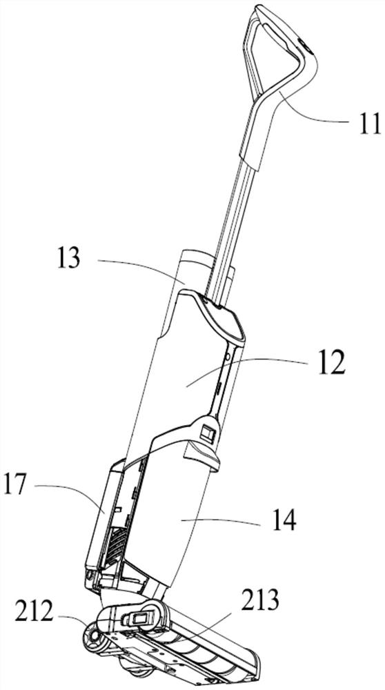
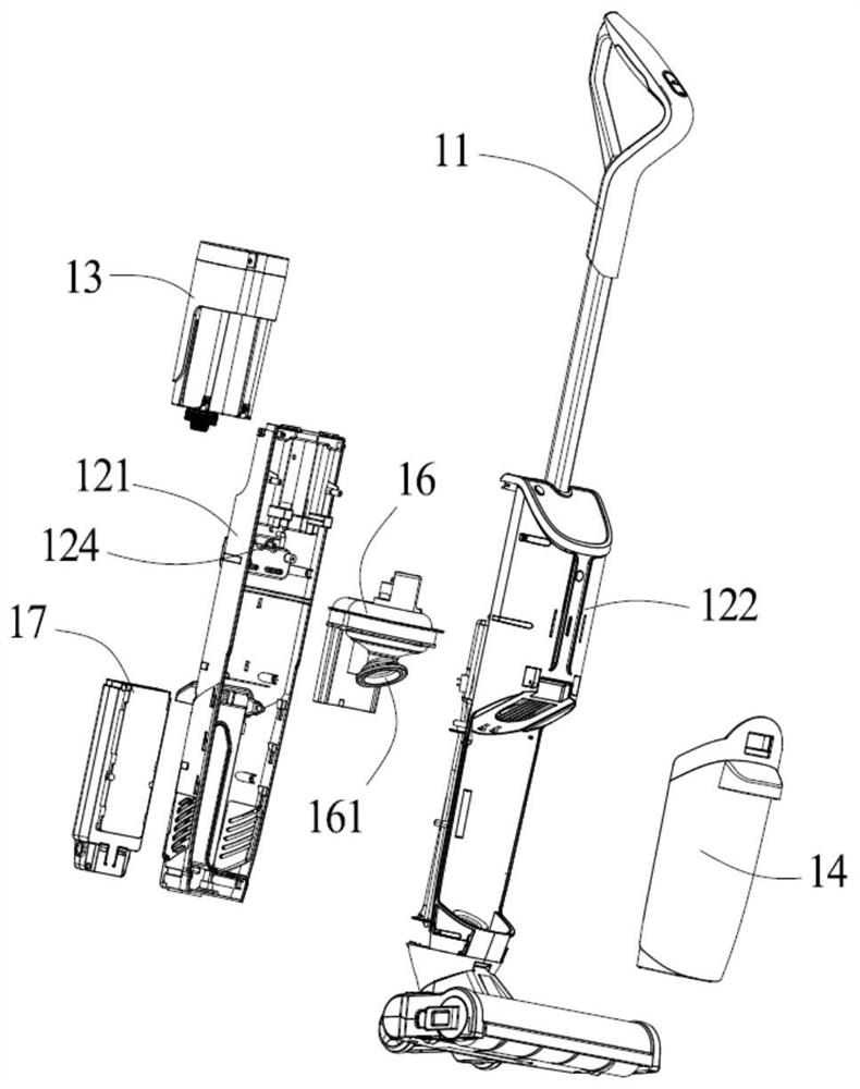
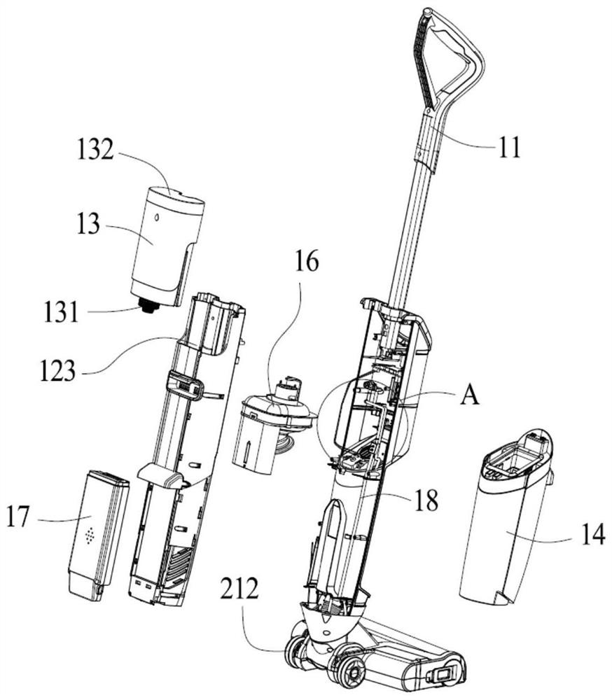
[0039] Such as Figures 1 to 8 As shown in , this embodiment is a floor washing machine. The floor washing machine includes a hand-held part and a base main unit. The supernatant water tank 13, the dirty water tank 14, the main control board 15, the fan unit 16 and the battery 17, and the housing include a front shell 121 and a rear shell 122 assembled with each other.

[0040] The base host includes a base 21 and an upper cover 22 installed on the base, an adapter 23, a water pump 24 and a roller brush mechanism, and the lower end of the rear shell of the hand-held part is connected with the adapter of the base.

[0041] The clean water tank 13 is detachably installed on the front shell 121, and the clean water tank 13 is equipped with a clean water tank cover 132 that can be opened for easy addition of clean water. The outlet 131 at the lower end of the tank is connected to a clean water joint 124 of the front shell, the clean water joint 124 is connected to the upper end o...

Embodiment 2

[0052] In the second embodiment, based on the structure of the washing machine in the first embodiment above, a water level alarm control method for the washing machine is proposed, including:

[0053] A detection component is installed on the outlet pipeline of the clean water tank to detect whether there is clean water in the water outlet pipeline; the detection component transmits the detected induction signal to the main control board; the main control board receives the detected induction signal, judges whether there is clean water, If the result of continuous judgment within the set time is that there is no clear water, an alarm signal will be given.

[0054] After the alarm signal is given, the main control board controls the washing machine to stop working and enter the standby state, and at the same time, an alarm sound is generated or a prompt message is generated on the display screen.

[0055] The preset time is 3 to 10 seconds, preferably 5 seconds. The problem of...


PUM


Abstract

The invention relates to a floor cleaning machine water level alarm control method. The method comprises the steps that detection components used for detecting whether clear water exists in a water outlet pipeline or not arae installed on the water outlet pipeline of a clear water tank; the detection components transmit detected induction signals to a main control board; and the main control board receives the detected induction signals, judges whether clear water exists or not, and gives an alarm signal if a continuous judgment result shows that no clear water exists within a preset time. The preset time is 3-10 seconds. A buffer box is installed on a water outlet pipeline of the clear water tank, the detection components are two metal terminals extending into the buffer box, and the two metal terminals are electrically connected with the main control board at the same time. The technical scheme has the beneficial effects that through the arrangement of the buffer box and the detection components, whether clear water in the clear water tank in the clear water tank is used up or not can be judged by detecting whether clear water exists in the buffer box or not, and then a signal is given to control the floor cleaning machine to send out a prompt or shut down to remind a user to add water in time.

Description

technical field [0001] The invention belongs to the technical field of floor washing machines, and relates to a water level alarm control method and system of a floor washing machine. Background technique [0002] Scrubbers are common cleaning products in daily life. They are mainly used to replace traditional vacuum cleaners, brooms and mops, and use electrical energy to convert mechanical energy to realize the functions of washing and vacuuming. Its working principle is to install a cleaning roller brush driven by a power component, and the periphery of the roller brush is provided with a cleaning layer made of flexible material, such as cotton cloth, sponge, engineering plastic or fiber, etc., to moisturize the cleaning layer Wet, the ground to be cleaned is scrubbed by the rotation of the roller brush to clean the ground and recycle the sewage or garbage. [0003] In order to wet the cleaning layer, the floor scrubber is equipped with a water tank, which includes a fres...

Claims


Application Information

Patent Timeline
Patent Type & Authority Applications(China)
IPC IPC(8): A47L11/292A47L11/40
CPCA47L11/292A47L11/4083A47L11/4088A47L11/4016A47L11/4011A47L11/4041
Inventor 沈伟先
Owner DONGGUAN SUN SMILE INTELLIGENT TECH CO LTD
Why Eureka
Try Eureka