Kitchen garbage crushing combined cutter

A technology of combining knives and kitchen waste, applied in the direction of grain processing, etc., can solve the problems of ineffective use, damaged knives, motor damage, etc., and achieve the effect of improving cutting and crushing effect, improving performance, and smooth processing.

Pending Publication Date: 2021-04-06
ANHUI JIANGHANG ENVITEK ENVIRONMENTAL TECH CO LTD
View PDF1 Cites 3 Cited by
  • Summary
  • Abstract
  • Description
  • Claims
  • Application Information

AI Technical Summary

Problems solved by technology

[0004] However, there are the following disadvantages in the prior art. Since the fixed blade is installed on the barrel wall, the cutting part is limited to the far end of the power output axis, resulting in a small cutting force and inconvenient adjustment under the condition of a certain power output torque, and it is difficult to crush hard Especially when encountering high hardness such as pig bones and beef bones, the cutters are often stuck and the motor is overloaded and damaged, or forced to stop, cutting and grinding are stopped, and the use effect cannot be achieved; Adhesive curing adheres to the tank wall, making it difficult to clean or even destroying the knives

Method used


Image

  • Kitchen garbage crushing combined cutter
  • Kitchen garbage crushing combined cutter
  • Kitchen garbage crushing combined cutter

Examples


Embodiment 1

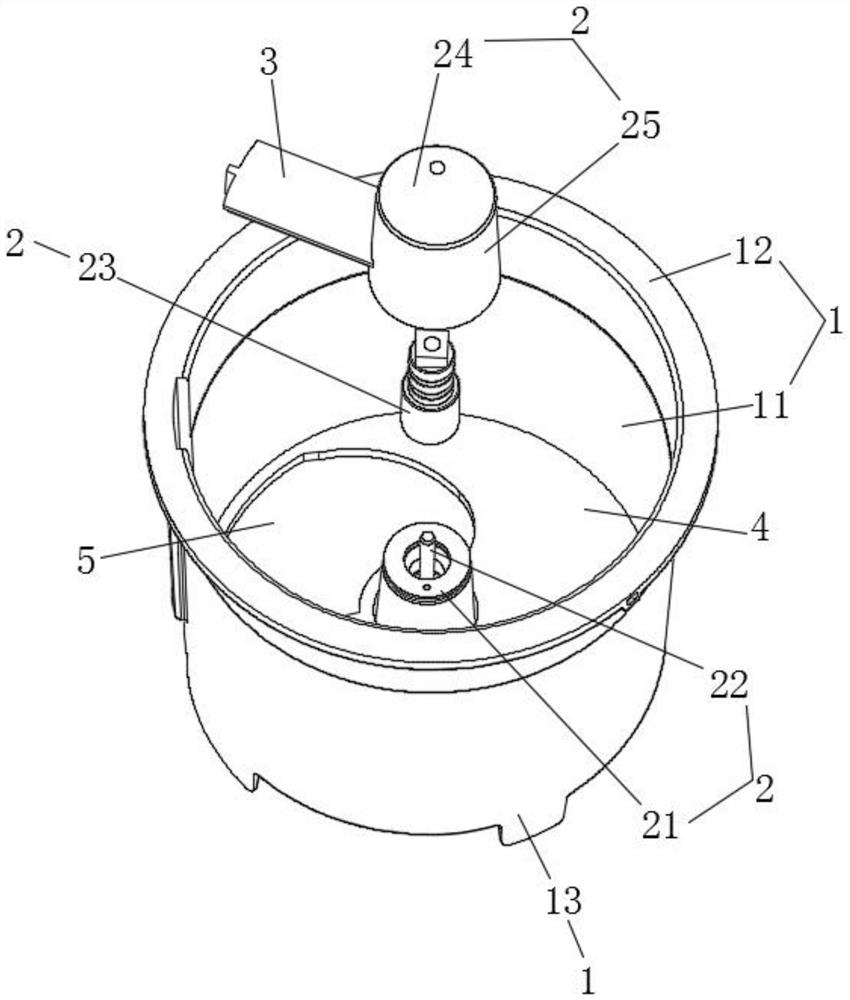
[0041] refer to figure 1 , the present embodiment discloses a kitchen waste shredding combined cutter, including a bucket 1 , a rotating assembly 2 , a cutting assembly 3 , a fixed blade 4 and an undercut 5 .

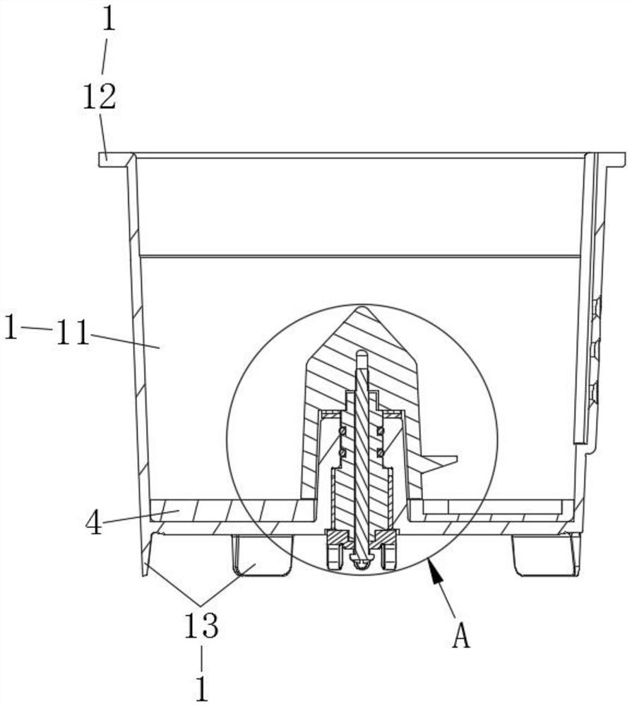
[0042] The barrel 1 includes a barrel body 11 , flanges 12 , and feet 13 . The opening of the barrel body 11 is bent outwards with a flange 12 . The bottom of the barrel body 11 is provided with three legs 13 distributed around the central axis of the barrel body 11 .

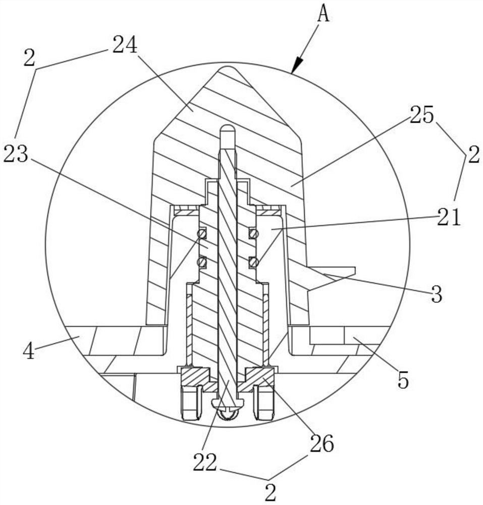
[0043] refer to Figure 4 and Figure 5 , the cutting assembly 3 includes a movable blade 31 . The movable blade 31 is welded outside the outer connecting sleeve 25 . And movable blade 31 is arranged on 2-3cm above fixed blade 4. The cutting edge of the moving blade 31 is towards the arc-shaped cutting edge of the bottom notch 5, and the cutting edge of the moving blade 31 performs a shearing movement relative to the cutting edge of the bottom cutting 5 to cut off the rubbish lump held between the ...

Embodiment 2

[0059] The difference from Embodiment 1 is that there are two sets of moving blades 31 , which are arranged up and down respectively, and the two sets of moving blades 31 are all welded on the outside of the outer connecting sleeve 25 . The fixed blades 4 have two groups, and are spaced up and down with the two groups of moving blades 31 . The bottommost fixed blade 4 is located below the bottommost movable blade 31 . Two groups of fixed blades 4 are all fixed on the barrel wall of the feed barrel 1.


PUM


Abstract

The invention discloses a kitchen garbage crushing combined cutter. The kitchen garbage crushing combined cutter comprises a material barrel, a cutting assembly, a fixed blade and a bottom notch, wherein, the fixed blade is fixed at the bottom in the material barrel; the cutting assembly comprises a movable blade; a rotating assembly capable of rotating is mounted at the bottom inside the material barrel; the rotating assembly rotates with the axis of the material barrel as the center; the movable blade is fixed on the lower half section of the rotating assembly; the movable blade is arranged above the fixed blade; at least one side of the fixed blade is provided with the bottom notch which is provided with an edge part and faces the cutting edge of the movable blade; and one ends of the bottom notches extend towards the center of the bottom of the material barrel. According to the kitchen garbage crushing combined cutter, harder garbage blocks can be cut through self-adaptive adjustment of a shearing force arm and shearing force, and the use performance is obviously improved; frequent cutter clamping and cutter damage in the cutting process are effectively avoided, manual intervention is reduced, the treatment process is smoother, and the effect is better; and the length of the cutting working section is increased, so that more garbage is cut at the same time, and the cutting and crushing efficiency is improved.

Description

technical field [0001] The invention relates to the technical field of kitchen waste treatment, in particular to a kitchen waste crushing combined cutter. Background technique [0002] Kitchen waste includes soft waste such as fruit peels and leaves, as well as hard substances such as fish bones and bones. In household kitchen waste disposal, the common way is to use high-speed cutting and crushing to discharge through the sewer. In recent years, a new low-speed processing method has emerged. It does not use large-scale crushing equipment or high-speed crushing devices with excessive noise. , the residues can be used as plant fertilizers, and are suitable for use in the home environment. The knives used in this type of equipment usually include one or several sets of moving blades and fixed blades. When food waste enters the gap between the relative movement of the moving and fixed blades, Junk blocks cut off. [0003] The reference document with the publication number ZL2...

Claims


Application Information

Patent Timeline
Patent Type & Authority Applications(China)
IPC IPC(8): B02C18/18B02C18/12B02C18/16B02C25/00
CPCB02C18/0092B02C18/12B02C18/16B02C18/18B02C25/00B02C2018/162B02C2201/06
Inventor 祝平安廖江伟
Owner ANHUI JIANGHANG ENVITEK ENVIRONMENTAL TECH CO LTD
Why Eureka
Try Eureka