Tea processing equipment
A kind of processing equipment and tea technology, which is applied in tea treatment before extraction, solid separation, filtration and sieving, etc. It can solve the problems of color, aroma, taste, shape, unsuitable for purchase, and easy breakage of tea leaves.
- Summary
- Abstract
- Description
- Claims
- Application Information
AI Technical Summary
Problems solved by technology
Method used
Image
Examples
Embodiment 1
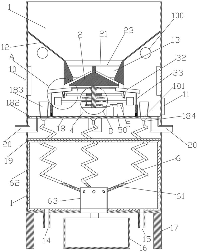
[0038] Such as figure 1 The tea automatic equipment shown includes a chassis 1 and a control panel 11 installed on the chassis 1, the control panel 11 is connected to an external power supply, and the bottom of the chassis 1 is provided with a foot 17,
[0039] The middle part of the cabinet 1 is provided with a clapboard 18, and a screening device is installed in the cabinet 1 above the clapboard 18, and a killing device is installed below the clapboard 18, and a material receiving cylinder 183 and a chip discharge port 182 are installed on the clapboard 18, and the material receiving The partition 18 at the bottom of the barrel 183 is provided with a discharge hole 181, and the chip discharge port 182 is equipped with a chip discharge pipe 20 communicating with the outside of the cabinet 1. The feeding tube 183 is connected with the killing device. Also be provided with heat insulating board 19 on the top, form the finishing box between heat shielding plate 19 and the bottom...
Embodiment 2
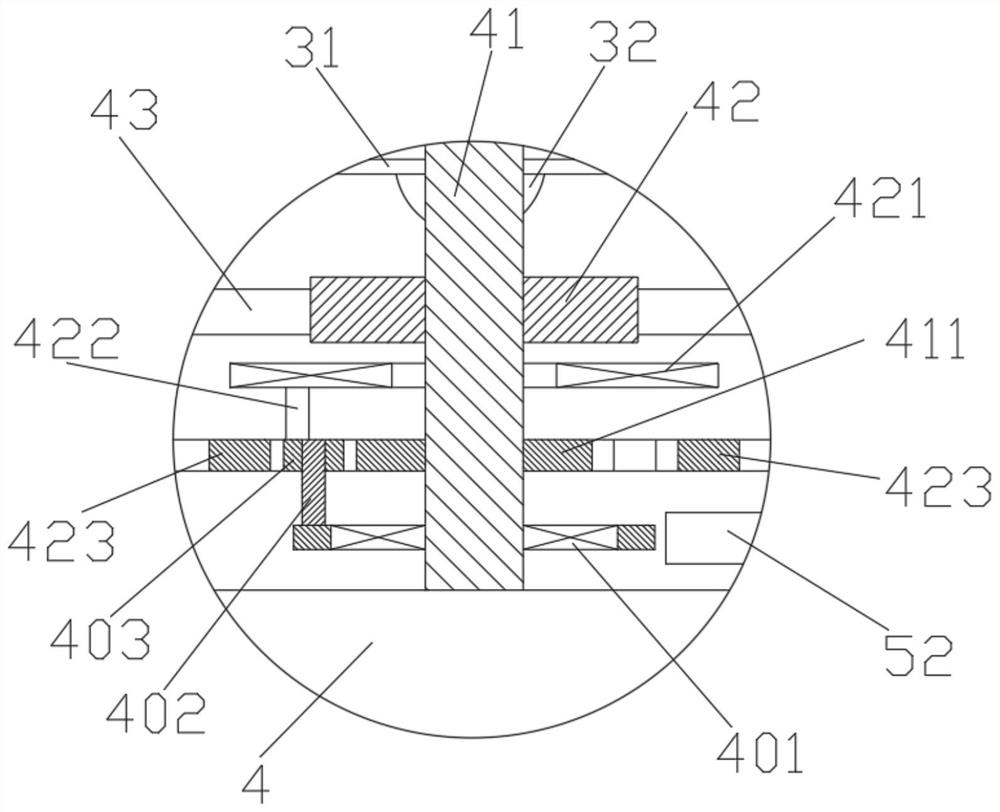
[0041] Such as Figure 2-9 As shown, the screening equipment includes an inverted cone-shaped stopper 12 arranged on the inner surface of the upper part of the cabinet 1 above the partition 18, and the bottom of the stopper 12 is connected with a feeding cylinder 13, and the upper part of the feeding cylinder 13 is an inverted cone Shaped structure, the lower part is a conical structure, the motor 4 electrically connected with the control panel 11 is installed on the partition 18 below the feeding cylinder 13, the motor 4 adopts a servo motor, the speed is adjustable, and the rotating shaft of the motor 4 is fixedly connected with a drive Rod 41, the top of driving rod 41 is equipped with the distributing device that is positioned at feed cylinder 13, and the bottom of distributing device is provided with screening device, and screening device is connected with dividing plate 18;
[0042] The distributing device includes a distributing cone 2 and a grid plate 23. Four distribu...
Embodiment 3
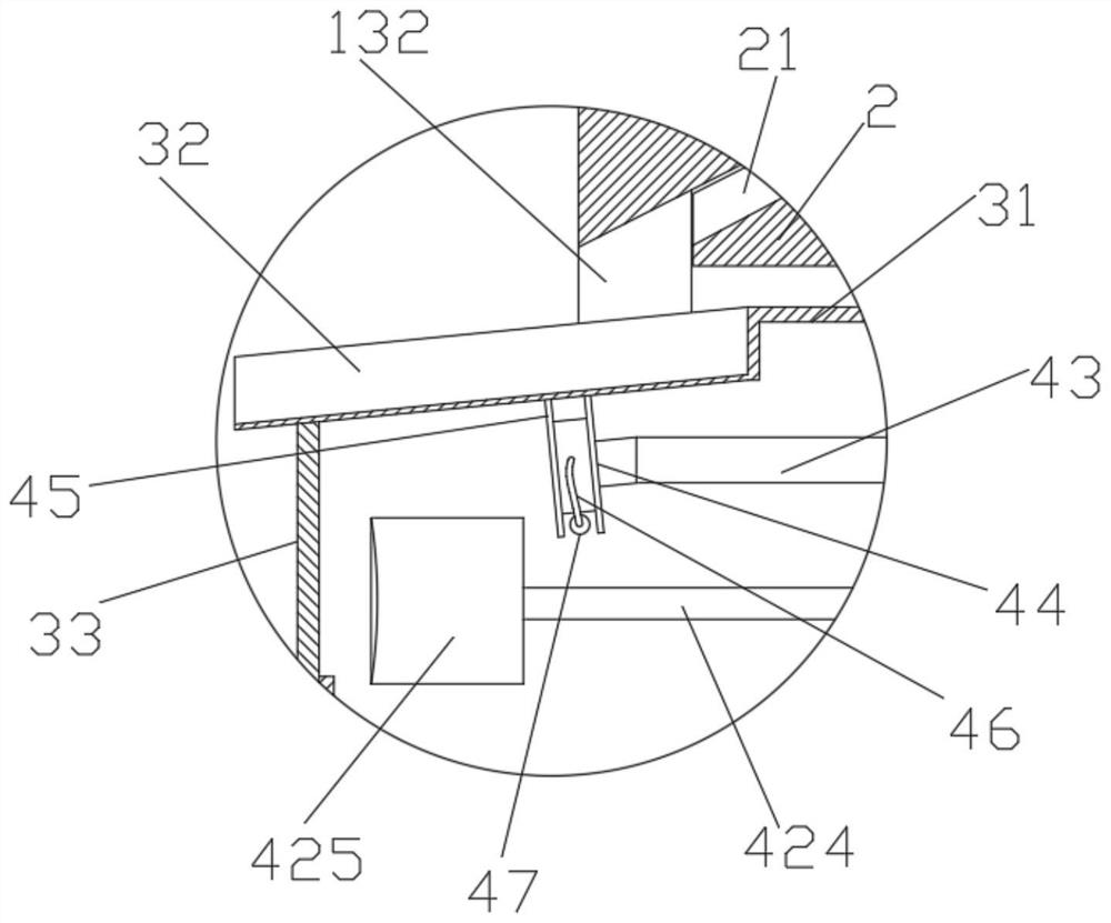
[0049] As a further technical solution of the present invention, an upper snap ring 42 is fixedly installed on the drive rod 41 between the speed changer and the ring disc 31, and a support rod 43 is fixedly installed on the outer surface of the upper snap ring 42, and the top end of the support rod 43 A roller 44 whose surface is perpendicular to the bottom of the screening channel 32 is installed. Two rubber ribs 45 parallel to each other and arranged around the surface of the roller 44 are arranged on the surface of the roller 44. Between the two ribs 45, the surface of the roller 44 An elastic ball 47 is connected through the soft rope 46 , and the diameter of the elastic ball 47 is smaller than the distance between the two convex ribs 45 and the height of the convex rib 45 . The roller 44 continuously impacts the bottom of each screening channel 32 with the rotation of the drive rod 41. At the same time, the roller 44 can rotate freely, which avoids the hard impact of the ...
PUM
 Abstract
Description
Claims
Application Information
 - R&D
- Intellectual Property
- Life Sciences
- Materials
- Tech Scout
- Unparalleled Data Quality
- Higher Quality Content
- 60% Fewer Hallucinations
Browse by: Latest US Patents, China's latest patents, Technical Efficacy Thesaurus, Application Domain, Technology Topic, Popular Technical Reports.
© 2025 PatSnap. All rights reserved.Legal|Privacy policy|Modern Slavery Act Transparency Statement|Sitemap|About US| Contact US: help@patsnap.com


