Wafer slicing machine

A slicing machine and wafer technology, which is applied in the field of wafer slicing machines, can solve the problems of affecting the dicing quality of wafers, the collapsed edge of the wafer being heated and rolling up, and the frictional heat being difficult to dissipate quickly.

Inactive Publication Date: 2021-04-06
尹强
View PDF0 Cites 2 Cited by
  • Summary
  • Abstract
  • Description
  • Claims
  • Application Information

AI Technical Summary

Problems solved by technology

[0004] When the diamond scribing knife of the slicer slices the wafer, due to the poor thermal conductivity of the wafer, the frictional heat generated by the friction between the scribing knife and the scribing knife is difficult to dissipate quickly during t...

Method used


Image

  • Wafer slicing machine
  • Wafer slicing machine
  • Wafer slicing machine

Examples


Embodiment 1

[0029] as attached figure 1 to attach Figure 6 Shown:

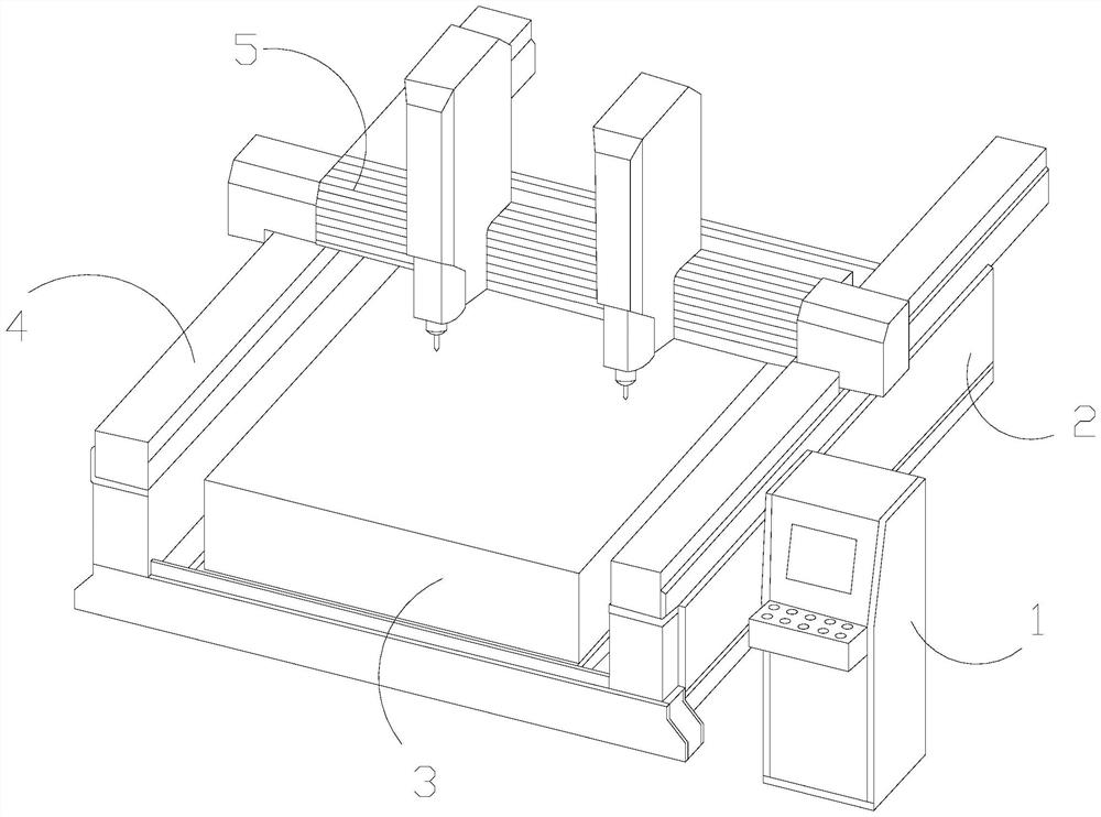
[0030] The invention provides a wafer slicing machine, the structure of which is provided with a console 1, a support base 2, a placement table 3, a side rail 4, and a working body 5, the console 1 is installed on the side end of the support base 2, and the The placement platform 3 is located at the interval section of the support seat 2, the side rail 4 and the support seat 2 are integrated structures and are arranged at both sides thereof, and the operating body 5 moves on the top surface end of the placement platform 3, so The two ends of the working body 5 are slidingly matched with the side rails 4 .

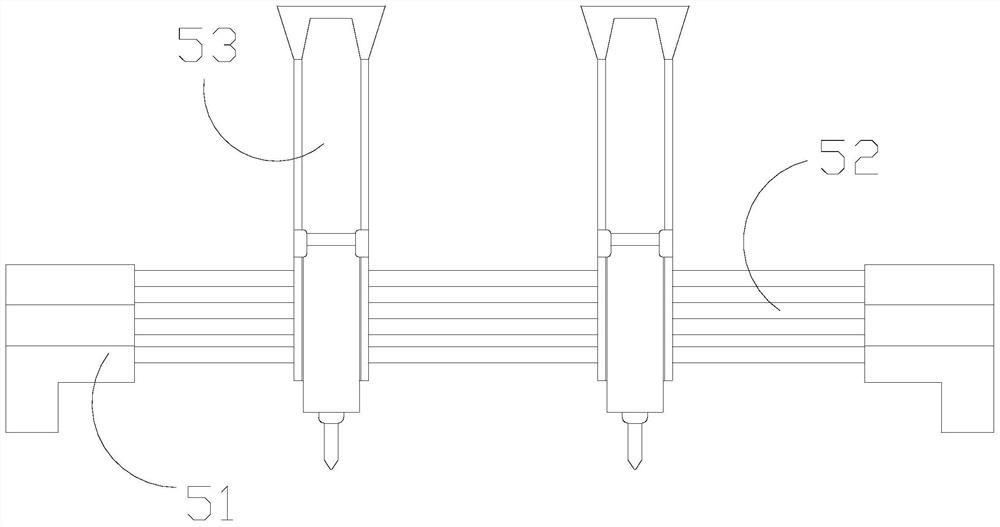
[0031] The working body 5 is provided with a buckle sliding end 51, a middle slide rail 52, and a cutting device 53. The buckle slide end 51 is embedded and connected to both ends of the middle slide rail 52, and the cutting device 53 is fastened and connected to the middle slide rail. 52 on and slip fit.

[0032]...

Embodiment 2

[0038] as attached Figure 7 To attach Figure 8 Shown:

[0039] Wherein, the scribing knife a4 is provided with a blade a41 and a circumferential groove a42, the circumferential groove a42 and the knife edge a41 are of an integrated structure and are arranged at its peripheral position, and the circumferential groove a42 is a groove on the blade a41. Groove cavity, which increases the contact area with the air, is the dredging surface for the increase of heat gas.

[0040] Wherein, the circumferential groove a42 is provided with a groove inner surface b1, a rotating block b2, and a spring b3. The loose blocks b2 are connected and movably matched. The scattered block b2 is embedded and movable on the front side of the inner surface b1 of the groove. The scattered block b2 is cross-shaped, and the elastic force of the spring b3 drives the scattered block b2 to swing back and forth. , so that the flow rate of the airflow can be changed to facilitate the flow of heat gas.

[...


PUM


Abstract

The invention discloses a wafer slicing machine. The wafer slicing machine is structurally provided with a control table, a supporting seat, a placing table, a side rail and an operation body. An integral connecting block is driven by a sliding connecting wheel to integrally do arc-direction expansion and compression movement, a mutual force spring assists the integral connecting block to reset, so that the integral connecting block circularly does arc-shaped opening and closing, gas circulates through a ventilation opening, and the flow speed of the gas is changed, and therefore, the airflow in the interior of a lower embedding area is actively changed; in the flowing process of the gas passing through a flow dredging cavity, and rotating body rotates to further drive the gas to flow and change the flow speed of the gas, so that the gas discharges downwards more quickly, blowing gas is generated at the lower end, and heat gas is advantageously blown away; a circumferential groove serves as a cavity groove additionally formed in a cutting edge, and therefore heat can be effectively homogenized; and a rotating scattering block is transversely embedded into the circumferential grooves in a penetrating mode, circularly swing in a radian mode under the elastic effect of a spring, and drive surrounding airflow to flow in the swinging process through the overall cross-shaped structure of the rotating scattering block, so that the airflow flowing force is increased, and diffusion of heat gas is facilitated.

Description

technical field [0001] The invention belongs to the field of wafer slicers used for chips, and more specifically relates to a wafer slicer. Background technique [0002] As a semiconductor material, wafers are usually produced and used in the form of wafers. Wafer slicers are processing machines for wafer sheet processing. Slicer scribing includes diamond scribing and laser scribing. The knife slits the wafer to obtain a wafer that meets the required size. [0003] Based on the inventor's discovery above, the existing wafer slicing machine has the following deficiencies: [0004] When the diamond scribing knife of the slicer slices the wafer, due to the poor thermal conductivity of the wafer, the frictional heat generated by the friction between the scribing knife and the scribing knife is difficult to dissipate quickly during the scribing process, and the scribing knife always carries Frictional heat will cause edge chipping during the scribing process. The heat will easi...

Claims


Application Information

Patent Timeline
IPC IPC(8): B28D5/04B28D7/02B28D7/00
CPCB28D5/0058B28D5/0064B28D5/0076B28D5/042
Inventor 尹强
Owner 尹强
Why Eureka
Try Eureka