Laser cladding alloy powder recovery equipment

A technology of alloy powder and recycling equipment, which is applied in metal processing equipment, metal material coating technology, transportation and packaging, etc., which can solve the problems of automatic grinding, manual screening and manual shaking of alloy powder, and achieve the collection effect Effect

Active Publication Date: 2021-04-06
江西鑫润材料科技有限公司
View PDF15 Cites 0 Cited by
  • Summary
  • Abstract
  • Description
  • Claims
  • Application Information

AI Technical Summary

Problems solved by technology

[0005] In order to overcome the shortcomings of alloy powders that cannot be automatically ground, manually screened and shaken, the technical problem to be solved is to provide a recycling equipment for laser cladding alloy powder that can realize automatic grinding, automatic screening and automatic shaking of alloy powder

Method used


Image

  • Laser cladding alloy powder recovery equipment
  • Laser cladding alloy powder recovery equipment
  • Laser cladding alloy powder recovery equipment

Examples


Embodiment 1

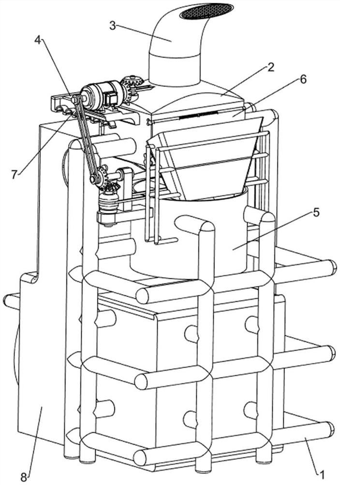
[0065] A recycling equipment for laser cladding alloy powder, such as figure 1 As shown, it includes a frame 1, a position frame 2, a dust suction mechanism 3 and a screening mechanism 4. A position frame 2 is provided on the upper part of the frame 1, a dust suction mechanism 3 is provided on the position frame 2, and a screening mechanism is provided on the inner wall of the position frame 2. Institution 4.

[0066]When people want to recycle alloy powder, they can use this equipment for recycling alloy powder for laser cladding. First, the user moves the device to the vicinity of the machine tool, starts the dust suction mechanism 3, and the dust suction mechanism 3 will remove the dust on the machine tool. The alloy powder is adsorbed into the screening mechanism 4, and the screening mechanism 4 screens and collects the alloy powder. After the alloy powder is collected, the dust suction mechanism 3 is closed.

Embodiment 2

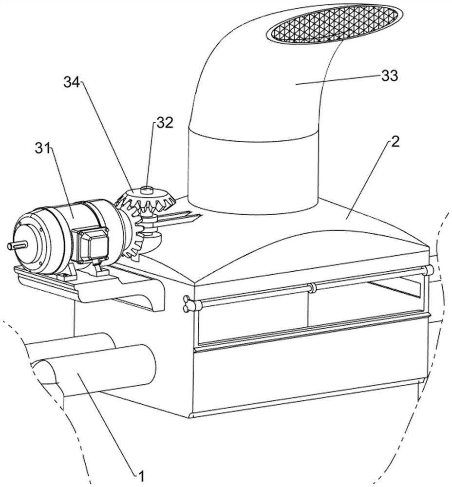
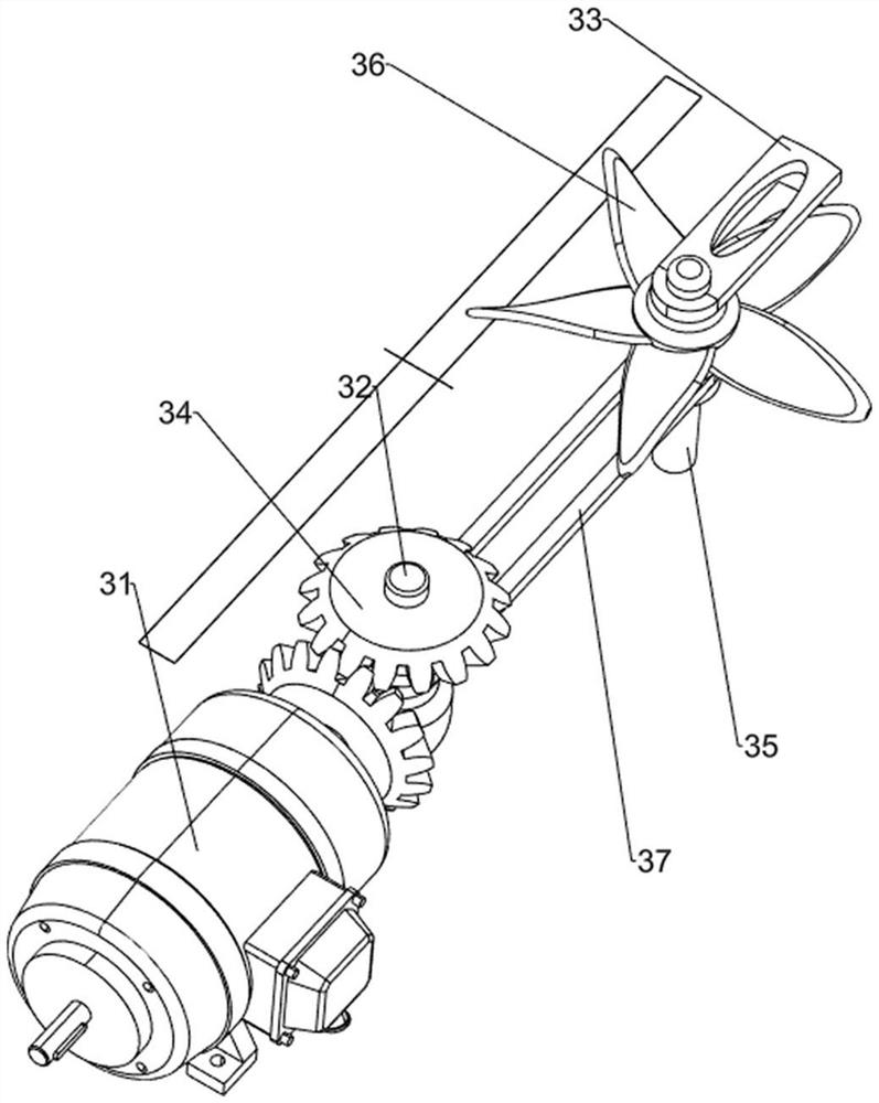
[0068] On the basis of Example 1, such as Figure 2-Figure 4 As shown, the dust suction mechanism 3 includes a bidirectional motor 31, a first transmission shaft 32, a suction nozzle 33, a first reversing gear set 34, a second transmission shaft 35, a fan piece 36 and a first pulley assembly 37, and the position frame 2 A two-way motor 31 is installed on the left side of the upper part, a first transmission shaft 32 is arranged on the top of the position frame 2, and a suction nozzle 33 is provided at the middle part of the position frame 2, and the output shaft on the right side of the two-way motor 31 is connected to the first transmission shaft 32 There is a first reversing gear set 34, the bottom of the suction nozzle 33 is rotatably provided with a second transmission shaft 35, the second transmission shaft 35 is provided with a fan piece 36, and there is a connection between the second transmission shaft 35 and the first transmission shaft 32 The first pulley assembly 37...

Embodiment 3

[0073] On the basis of Example 2, such as Figure 5-Figure 10 Shown, also comprise door-opening mechanism 5, position frame 2 front sides are provided with door-opening mechanism 5, door-opening mechanism 5 includes jacking plate 51, fixed shaft 52, swinging plate 53 and torsion spring 54, pushing plate 41 front walls left and right sides Both sides are provided with jacking plate 51, and position frame 2 front portion is provided with fixed shaft 52, and the fixed shaft 52 is connected with swinging plate 53 in rotation, swinging plate 53 top left and right sides are all covered with torsion spring 54, and torsion spring 54 two The ends are respectively connected with the swing plate 53 and the fixed shaft 52.

[0074] Alloy powder with unequal volume remains on the position frame 2. When the pusher plate 41 moves forward, the pusher plate 41 drives the jacking plate 51 to move forward, and the pusher plate 41 pushes the alloy powder forward, which meets the standard The all...


PUM


Abstract

The invention relates to recovery equipment, in particular to laser cladding alloy powder recovery equipment. According to the laser cladding alloy powder recovery equipment, automatic grinding, automatic screening and automatic shaking of alloy powder are achieved. The laser cladding alloy powder recovery equipment comprises an enclosing frame, a dust collection mechanism and a screening mechanism; a position frame is arranged on the upper portion of the enclosing frame; the dust collection mechanism is arranged on the position frame; and the screening mechanism is arranged on the inner wall of the position frame. According to the laser cladding alloy powder recovery equipment, fan blades rotate in a suction nozzle to generate suction force, alloy powder on the surface of a machine tool is adsorbed into the suction nozzle and falls into the position frame through the suction nozzle, and the dust collection effect is achieved; and a telescopic assembly on the left side is compressed, and a telescopic assembly on the right side is stretched, so that a pushing plate is driven to move forwards, residual alloy powder is pushed into through holes, and the screening effect is achieved.

Description

technical field [0001] The invention relates to a recycling device, in particular to a recycling device for laser cladding alloy powder. Background technique [0002] During the laser cladding process, the pre-set coaxial powder feeding method is used for cladding. When the parts are rotating, the wear-resistant and corrosion-resistant metal powder preset on the parts will fall to the ground with the rotation of the parts. When the laser acts on the powder, a small amount of wear-resistant and corrosion-resistant metal powder and slag will also be precipitated. If this part of the powder is not recycled, the production cost will increase. Although there is no change in the composition of these powders, they are still It maintains the performance of wear resistance and corrosion resistance, but when it falls on the ground, it is mixed with more dust and impurities, and contains a large number of large oxide particles, so it cannot be directly used for cladding operations, and...

Claims


Application Information

Patent Timeline
IPC IPC(8): C23C24/10B22F9/04B22F1/00B07B1/28B08B5/04
CPCC23C24/103B22F9/04B07B1/28B08B5/04B22F2009/041B22F1/14Y02P10/25
Inventor 周海生
Owner 江西鑫润材料科技有限公司
Why Eureka
Try Eureka