Wind power generation device with roof reinforced concrete frame

A technology of wind power generation equipment and reinforced concrete, which is applied in the direction of wind power generator components, wind power engines, and wind power motor combinations, etc., and can solve problems such as poor wind gathering ability of the air gathering door, inflexible opening and closing of the air discharge door, and poor rigidity of the supporting frame structure, etc. , to achieve the effect of improving the utilization rate of wind energy, overcoming the frequent failure of limit switches and high verticality

Inactive Publication Date: 2012-10-17
李树广 +2
View PDF9 Cites 2 Cited by
  • Summary
  • Abstract
  • Description
  • Claims
  • Application Information

AI Technical Summary

Problems solved by technology

[0007] The purpose of the present invention is to solve the problems of low wind power utilization rate in the existing roof wind power generation system, poor wind gathering ability of the air gathering door, inflexible opening and closing of the air discharge door, poor rigidity of the supporting frame structure, low

Method used


Image

  • Wind power generation device with roof reinforced concrete frame
  • Wind power generation device with roof reinforced concrete frame
  • Wind power generation device with roof reinforced concrete frame

Examples


specific Embodiment approach 1

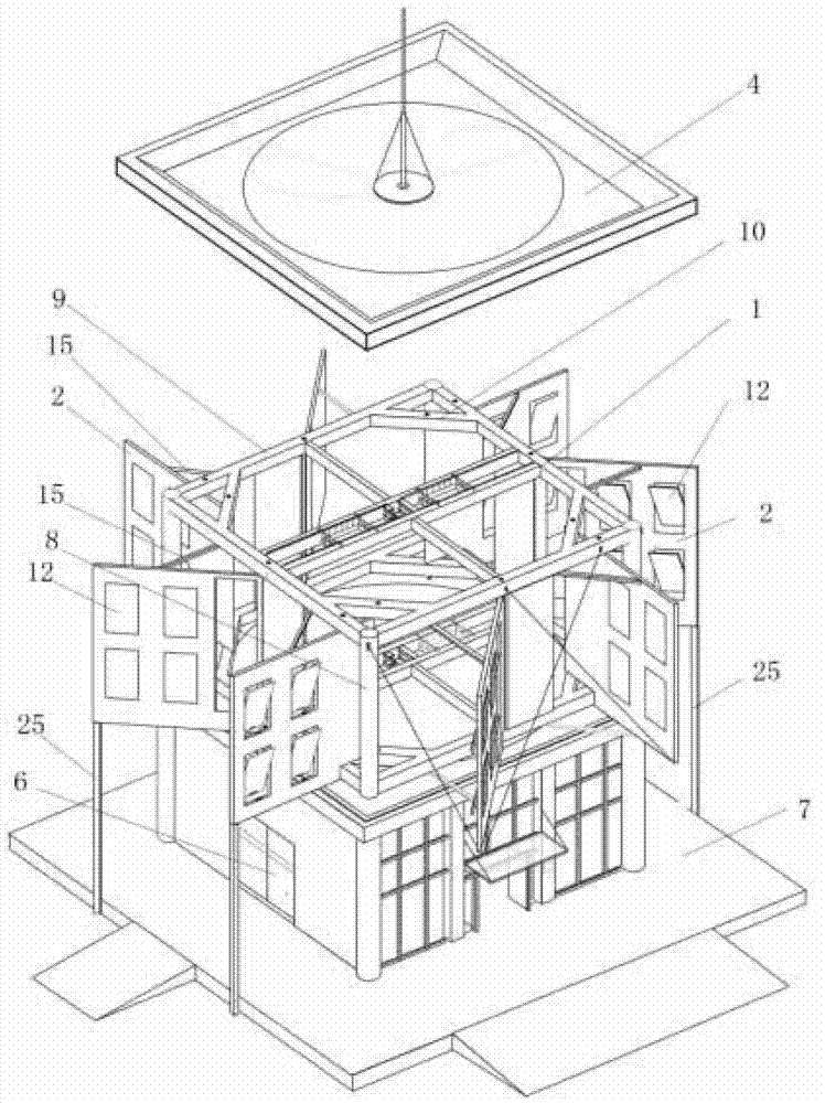
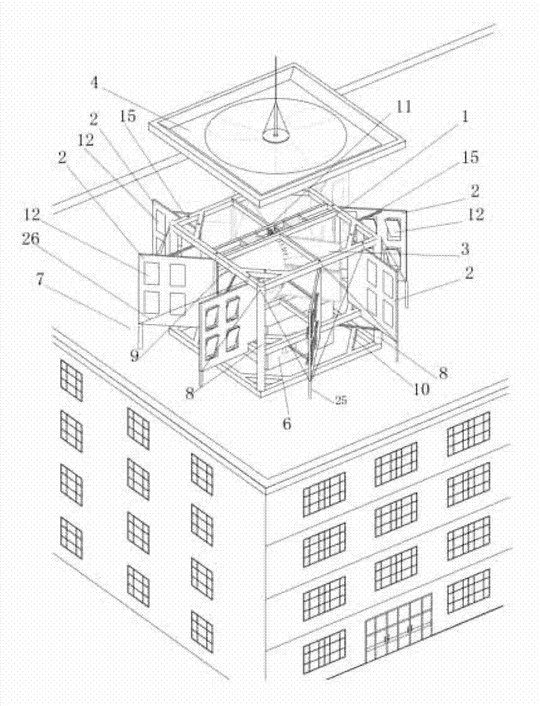
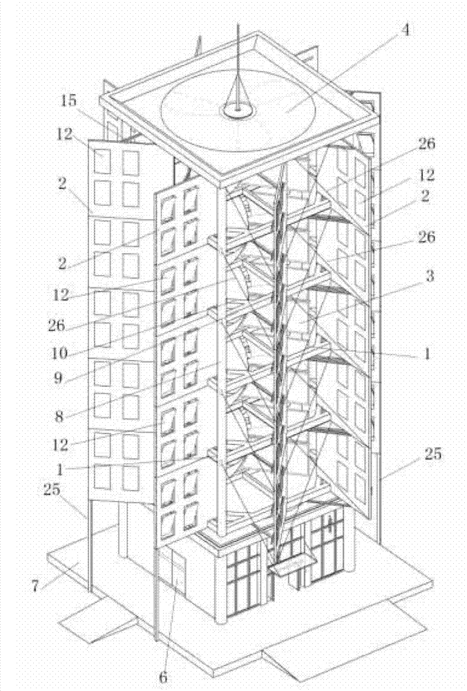
[0052] Specific implementation mode one: combine figure 1 , figure 2 , Figure 5-Figure 15 and Figure 18 Describe this embodiment, the roof reinforced concrete frame wind power generation equipment of this embodiment includes a reinforced concrete frame 1, eight wind deflectors 2, a wind power system 3, a top cover 4, a generator 5, a control room 6 and base platform 7,

[0053] The reinforced concrete frame 1 includes four reinforced columns 8, two four-sided beams 9, a plurality of cable-stayed beams 10 and two cross machine bearing beams 11;

[0054] Two four-sided beams 9 are set up and down, and the edges and corners of the two four-sided beams 9 are connected by reinforcing columns 8. Each four-sided beam 9 is provided with a cross machine bearing heavy beam 11, and each cross machine bearing heavy beam 11 is formed by a single beam 11 -1 and a double beam 11-2, each corner of the four-sided beam 9 is connected with a cable-stayed beam 10;

[0055] The reinforced ...

specific Embodiment approach 2

[0062] Specific implementation mode two: combination Figure 6 Describe this embodiment, the extension line 21 of the upper connecting end and the lower connecting end of the eight air discharge deflectors 2 of this embodiment and the motion locus circle 22 intersection point 23 of the wind blade 19 is the eighth of the motion locus circle of the wind blade 19. At the equal point, the angle A formed between the extension line 21 and the tangent line 24 passing through the intersection point 23 is 45 degrees to 50 degrees, and the adjacent two wind deflectors 2 are set at an angle of 45 degrees, and adjacent Among the two wind deflectors 2, the wind deflector near the edges and corners is perpendicular to the beam plate 9-1 of the four-side beam 9 on the side where it is installed, and the other of the adjacent two wind deflectors 2 The wind guide plate is positioned at the middle position of the beam plate 9-1 of the four side beam 9 on the installation side. Such setting can...

specific Embodiment approach 3

[0063] Specific implementation mode three: combination figure 1 To illustrate this embodiment, the roof reinforced concrete frame wind power generation equipment of this embodiment also includes six support columns 25 and two sets of tie bars 26, and the two wind-discharging guides on the front of the roof reinforced concrete frame wind power generation equipment The plate 2 is connected with the reinforcement column 8 and the four side beams 9 through two sets of tie bars 26 , and the bottom outer edge of the rest of the wind deflector 2 is supported on the ground through a support column 25 . Such arrangement prevents the wind deflector 2 from dropping corners, and the installation structure of the wind deflector is more stable, especially suitable for high-power wind power generation equipment in which the base platform 7 is set on the ground. Other compositions and connections are the same as those in Embodiment 1 or Embodiment 2.


PUM


Abstract

The invention discloses a wind power generation device with a roof reinforced concrete frame, relating to a wind power generation device. According to the wind power generation device with the roof reinforced concrete frame disclosed by the invention, the problems of the traditional roof wind power generation system that the wind power utilization rate is low, the wind power collection ability is poor, a wind release door is not flexible to open and close and the rigidity of a support frame structure is poor are solved. The wind power generation device with the roof reinforced concrete frame is a multi-layer wind power generation system or a single-layer wind power generation system, the reinforced concrete frame comprises a reinforced vertical column, a four-sided beam, a slanting beam and a cross machine bearing heavy beam, wind release deflectors are arranged at the periphery of the reinforced concrete frame and are connected with the reinforced concrete frame through embedded parts, wind is released through a wind release door on each wind release deflector, electromagnets or permanent magnets are embedded in the bottoms of the wind release doors and the bottoms of wind release ports to control the wind release doors to open and close, a combination shaft is in a segmented structure, a bearing component is arranged at the intersection part of an upper segment shaft, a lower segment shaft and double beams, a bearing seat tray is sleeved on the combination shaft, and air blades are installed on a middle segment at intervals with 120 degrees. The wind power generation device with the roof reinforced concrete frame is used for wind power generation.

Description

technical field [0001] The invention relates to wind power generation equipment, in particular to a roof reinforced concrete frame wind power generation equipment, which belongs to the technical field of wind power generation. Background technique [0002] Due to the limited amount of earth's energy reserves, with continuous exploitation, it will become increasingly depleted and in short supply, threatening the survival and development of human beings. When people use energy, they feel that the energy being used has caused harm to humans at the same time. Over-exploitation and logging have seriously damaged the living environment of human beings; such as the shortage of drinking water, the decline of air quality, and the increase in radiation. Therefore, how to rationally utilize natural energy (such as solar energy, wind energy, etc.) is a problem that must be solved today. Wind power generation is one of the measures to rationally utilize natural energy. [0003] As we a...

Claims


Application Information

Patent Timeline
IPC IPC(8): F03D9/00F03D11/00F03D3/02F03D3/04F03D9/25F03D9/45F03D13/20F03D80/00F03D80/70
CPCY02E10/74Y02B10/30
Inventor 李树广张井义
Owner 李树广
Why Eureka
Try Eureka