Multi-dimensional force acquisition method based on parallel rod system multi-dimensional force sensor

A technology of multi-dimensional force sensor and acquisition method, which is applied in the direction of measuring the component of force, the measurement of the property force of the application of piezoelectric devices, instruments, etc., and can solve the problems of low precision of multi-dimensional force, complicated calculation process, and small structural rigidity of the sensor.

Active Publication Date: 2021-04-06
马洪文 +1
View PDF20 Cites 4 Cited by
  • Summary
  • Abstract
  • Description
  • Claims
  • Application Information

AI Technical Summary

Problems solved by technology

[0011] The present invention aims to solve the problems of low precision of multi-dimensional force obtained by the existing multi-dimensional force sensor (mainly due to excessive inter-dimensional coupling), small structural stiffness of the sensor, too complicated calculation process and poor real-time performance, etc.

Method used


Image

  • Multi-dimensional force acquisition method based on parallel rod system multi-dimensional force sensor
  • Multi-dimensional force acquisition method based on parallel rod system multi-dimensional force sensor
  • Multi-dimensional force acquisition method based on parallel rod system multi-dimensional force sensor

Examples


specific Embodiment approach 1

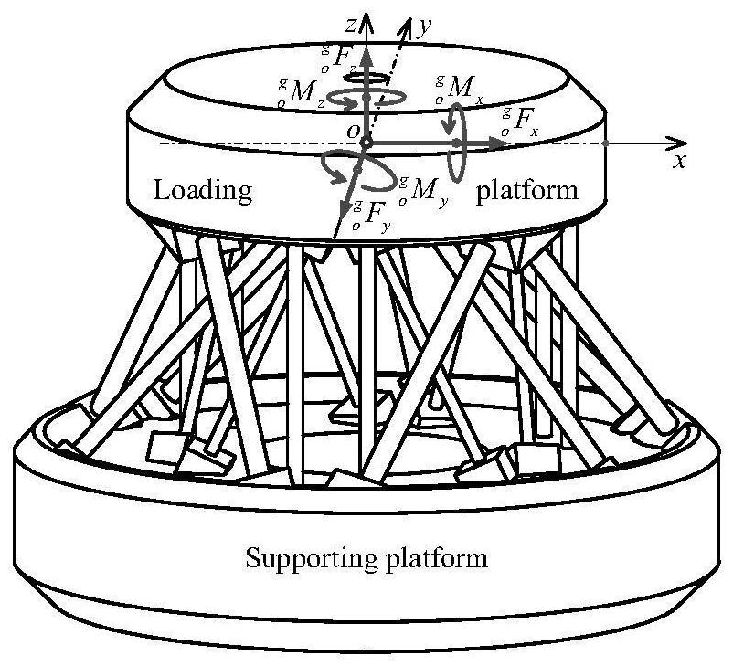
[0088] Parallel rod system multi-dimensional force sensor, such as figure 1 As shown, the support platform and the load platform are rigid bodies (in practical applications, both the support platform and the load platform are pseudo-rigid bodies, that is, approximate rigid bodies with minimal deformation), and the load platform and the support platform are connected by a parallel rod system (multiple strain beams) , the strain beam in the parallel bar system is used as the elastic sensitive element;

[0089] A micro-displacement measurement sensor is arranged between the support platform and the load platform to measure the micro-displacement between the two (caused by the deformation of the strain beam). The micro-displacement measurement sensor includes electrical, optical displacement sensors and other non-contact or micro-force contact sensors; electrical Displacement sensors generally use electrical sensors such as capacitance, inductance, and eddy current, and optical di...

specific Embodiment approach 2

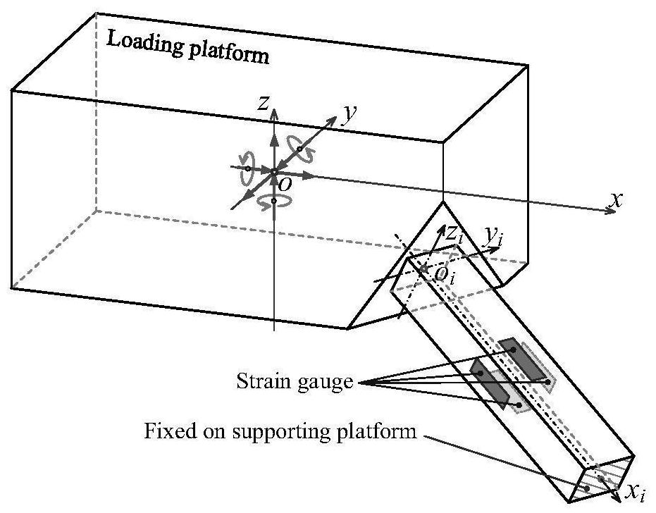
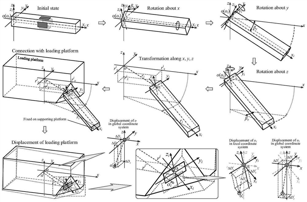
[0096] Before describing this embodiment, the representation form of the space vector symbol of the present invention is firstly described, for example The whole of each parameter is described as a form;

[0097] The main body of the symbol represents a space vector, Q represents a generalized force including force and moment, F represents a force, and M represents a moment; Δ represents a generalized deformation including displacement and rotation angle deformation, ΔD represents displacement deformation, Δθ represents rotation angle deformation; r represents a strain beam The distance between the origin of the local coordinate system and the origin of the global coordinate system in the global coordinate system, β represents the rotation angle of the local coordinate system of the strain beam around the three axes of the global coordinate system;

[0098] The superscript on the upper left corner represents the coordinate system, the upper corner on the upper left corner i...

specific Embodiment approach 3

[0160] According to this embodiment, the micro-displacement of the load platform in six directions under the action of external force is measured by the micro-displacement measuring sensor arranged between the support platform and the load platform. The specific process is as follows:

[0161] The measurement of the displacement of the load platform can use a non-contact electrical displacement sensor or an optical displacement sensor or a micro-force contact displacement sensor:

[0162] As shown in Figure 9, Figure 9(a) is a capacitive sensor, only x j The displacement on the axis has an effect on the capacitive displacement sensor; Figure 9(b) is a triangular light sensor, and only x j The displacement on the axis has an effect on the triangular optical displacement sensor;

[0163] As shown in Figure 10(a) and Figure 10(b), the local coordinate system of the displacement sensor attached to the displacement sensor is established, and the displacement direction measured by ...


PUM


Abstract

The invention discloses a multi-dimensional force acquisition method based on a parallel rod system multi-dimensional force sensor, belongs to the technical field of sensor measurement, and aims to solve the problems that multi-dimensional force obtained by an existing multi-dimensional force sensor is large in inter-dimensional coupling, low in precision, small in structural rigidity of the sensor and the like. According to the method, a vector transformation relation matrix between a local coordinate system and a global coordinate system is established, considerable measurement is obtained according to local deformation displacement of an origin of a load platform coordinate system along / around a measurement axis under a local coordinate system, and deformation displacement of a load platform under the global coordinate system is calculated; all local deformation displacements of the corresponding local coordinate origin of each strain beam under the local coordinate system are calculated according to the deformation displacement of the load platform under the global coordinate system, and the local generalized force of each strain beam under the local coordinate system is calculated according to the local deformation displacement of each strain beam under the local coordinate system; and the linear equation set is solved to obtain the multi-dimensional force of the multi-dimensional force sensor. The method is mainly used for multi-dimensional force acquisition of the multi-dimensional force sensor.

Description

technical field [0001] The invention belongs to the technical field of sensor measurement and relates to a method for acquiring force of a multi-dimensional force sensor. Background technique [0002] The multi-dimensional force sensor can detect the information of force acting in space, among which a typical six-dimensional force sensor can obtain 3 component forces and 3 moments formed by the force in the space coordinate system. In aerospace manipulators, aerospace docking, collaborative robots, bionic machinery, medical aids, walking robots, wind tunnel force measurement, aerospace engine thrust testing, propeller thrust testing, automobile crash testing, minimally invasive surgical robots, grinding and polishing equipment, stirring The six-dimensional force sensor plays an important role in many fields such as friction welding and machine tool processing force measurement, and the accuracy of the obtained six-dimensional force directly affects the working performance an...

Claims


Application Information

Patent Timeline
Patent Type & Authority Applications(China)
IPC IPC(8): G01L5/16G01L5/167G01L5/165
CPCG01L5/16G01L5/167G01L5/165G01L1/22G01L1/16
Inventor 马洪文邢宇卓
Owner 马洪文
Why Eureka
Try Eureka