
Liquid crystal display screen compression resistance detection method

A technology of liquid crystal display screen and detection method, which is applied in the direction of applying stable tension/pressure to test the strength of materials, measuring devices, optics, etc. Detection and other issues to achieve the effect of improving safety

Active Publication Date: 2021-04-06
深圳市永嘉视科技有限公司
View PDF12 Cites 10 Cited by
  • Summary
  • Abstract
  • Description
  • Claims
  • Application Information

AI Technical Summary

Problems solved by technology

[0006] The purpose of the present invention is to provide a liquid crystal display anti-pressure detection method to solve the problem that some liquid crystal display screens will be damaged during pressure detection due to unqualified quality in the prior art proposed in the above background technology. There is a phenomenon that it cannot withstand the test pressure and breaks. After the LCD screen is broken, the debris of the LCD screen will adhere to the bottom of the pressure detection board, which will affect the normal detection of the subsequent pressure resistance of the LCD screen. Manual inspection of the debris is required. However, when manually cleaning the debris on the LCD screen, it is necessary to reserve a certain amount of downtime for cleaning, which indirectly leads to a decrease in the efficiency of pressure detection. In addition, when cleaning the debris on the LCD screen, it may also cause personal injury. question

Method used


Image

  • Liquid crystal display screen compression resistance detection method
  • Liquid crystal display screen compression resistance detection method
  • Liquid crystal display screen compression resistance detection method

Examples


Embodiment Construction

[0035] The following will clearly and completely describe the technical solutions in the embodiments of the present invention with reference to the accompanying drawings in the embodiments of the present invention. Obviously, the described embodiments are only some, not all, embodiments of the present invention. Based on the embodiments of the present invention, all other embodiments obtained by persons of ordinary skill in the art without creative efforts fall within the protection scope of the present invention.

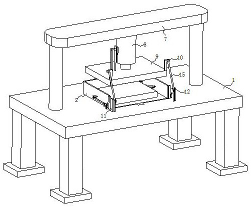
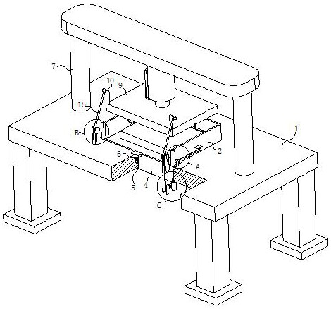
[0036] see Figure 1-11 , the present invention provides a technical solution: a liquid crystal display anti-pressure detection method, the specific steps of the detection method are:

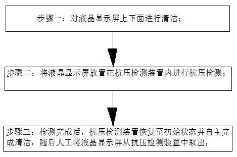
[0037] Step 1: Clean the top and bottom of the LCD screen;

[0038] Step 2: Place the liquid crystal display in the anti-pressure testing device for anti-pressure testing;

[0039] Step 3: After the test is completed, the anti-pressure detection device returns to the initial state...


PUM


Abstract

The invention discloses a liquid crystal display screen compression resistance detection method in the technical field of liquid crystal display screen compression resistance detection. The detection method comprises the specific steps that: step 1, the upper face and the lower face of a liquid crystal display screen are cleaned; step 2, the liquid crystal display screen is placed in a compression resistance detection device to be subjected to compression resistance detection; and step 3, after detection is completed, the compression resistance detection device returns to the initial state and autonomously completes cleaning, and then the liquid crystal display screen is manually taken out of the compression resistance detection device. A U-shaped anti-sputtering plate is in butt joint with a front-end anti-sputtering plate to form a sealed detection space, splashing of liquid crystal disintegrating slag is avoided, and when a pressure detection plate rises, a scraper is automatically driven to clean the bottom surface of the pressure detection plate, so that the disintegrating slag falls into the U-shaped anti-sputtering plate; and then a pushing-out mechanism is used for automatically discharging all the disintegrating slag collected in the U-shaped anti-sputtering plate, manual cleaning is not needed, and the disintegrating slag on the pressure detection equipment is thoroughly cleaned.

Description

technical field [0001] The invention relates to the technical field of anti-pressure detection of liquid crystal display screens, in particular to a method for anti-pressure detection of liquid crystal display screens. Background technique [0002] During the production process of liquid crystal display, it is necessary to carry out anti-pressure testing on the display screen. If the product is unqualified, it cannot be put into the market and will be regarded as a defective product. Therefore, the continuous operation of a manufacturer must ensure the quality of the product. Therefore, the resistance of the display screen Pressure detection is particularly important. [0003] In the invention case of liquid crystal display anti-pressure detection disclosed in the prior art, the Chinese patent application number of the invention patent is CN201920962597.6, a kind of anti-pressure detection device for liquid crystal display production, including an operation table, and the bo...

Claims


Application Information

Patent Timeline
Patent Type & Authority Applications(China)
IPC IPC(8): G02F1/13G01N3/12G01N3/02
CPCG01N3/02G01N3/12G01N2203/0019G01N2203/0044G01N2203/0067G02F1/1309
Inventor 周子琦方平陈林桂江艳
Owner 深圳市永嘉视科技有限公司
Learn More