
Pair of quick optical cable stripping pliers

A technology of wire strippers and optical cables, which is applied in the direction of cable installation, cable installation devices, equipment for dismantling/armoring cables, etc., and can solve the problems of increased man-hours and costs, cable core damage, and uneven force applied to the height of the stripping tool and other problems, to achieve the effect of convenient stripping, uniform pressure, and improved stripping efficiency

Pending Publication Date: 2021-04-06
国网浙江省电力有限公司开化县供电公司
View PDF5 Cites 0 Cited by
  • Summary
  • Abstract
  • Description
  • Claims
  • Application Information

AI Technical Summary

Problems solved by technology

[0004] The present invention is to overcome that the optical cable stripping device in the prior art can only strip the optical cable horizontally, and the fixed height of the stripping tool is easy to use uneven force to cause damage to the cable core. It is necessary to use other tools to strip the cable sheath along the radial direction of the optical cable to increase the man-hour. To solve the problem of cost, provide a fast optical cable stripper with uniform force, adjustable blade height, and suitable for horizontal and vertical stripping

Method used


Image

  • Pair of quick optical cable stripping pliers
  • Pair of quick optical cable stripping pliers
  • Pair of quick optical cable stripping pliers

Examples


Embodiment

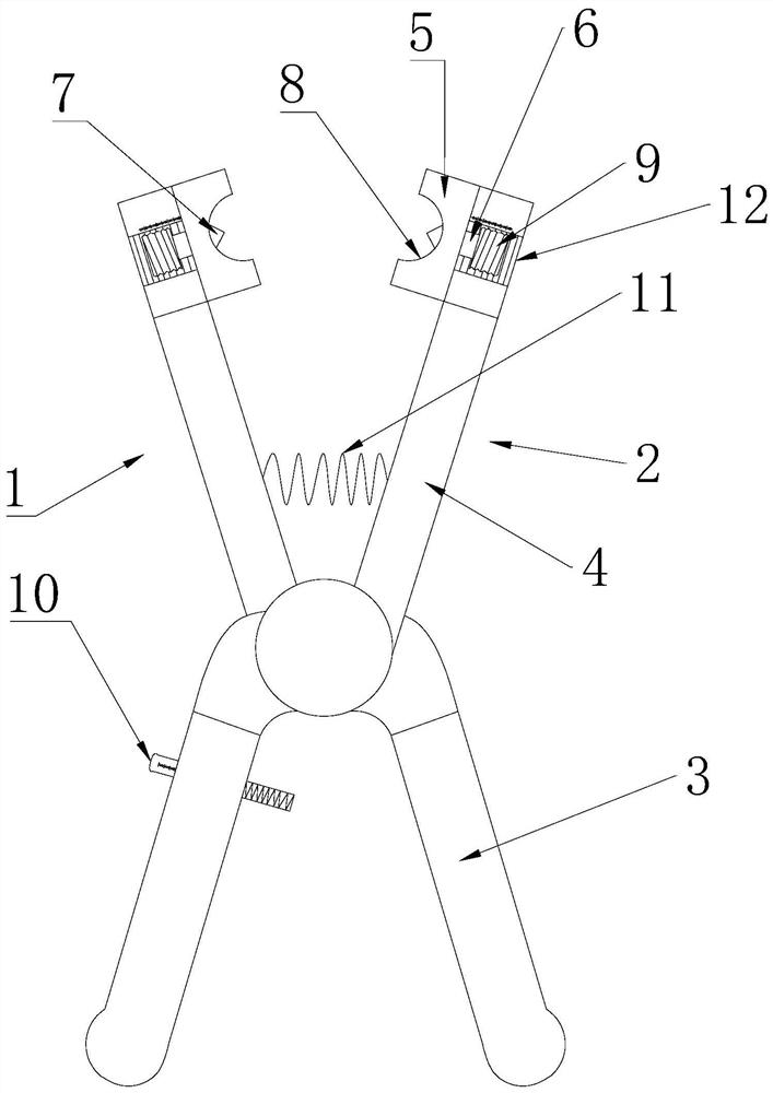
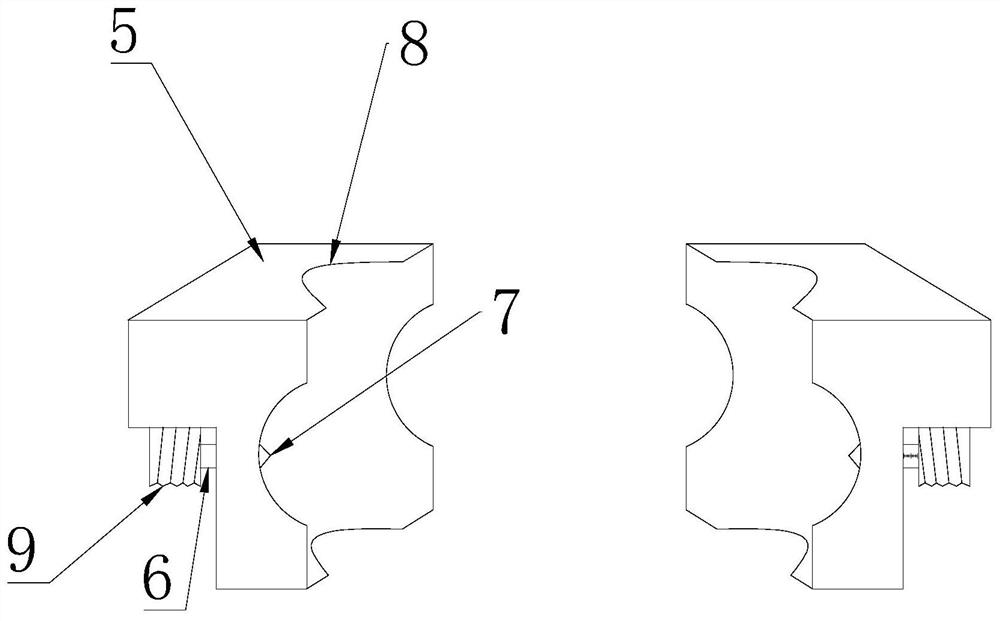
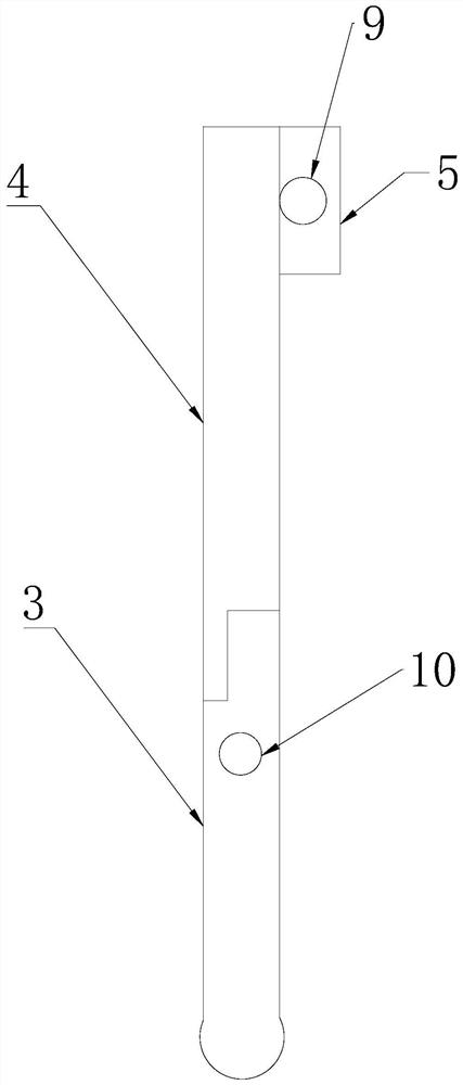
[0023] Such as Figure 1~3 In the shown quick stripping pliers for optical cables, the middle parts of the first pliers body 1 and the second pliers body 2 are staggered and hinged, and the first pliers body 1 and the second pliers body 2 include a holding section 3 and a working section 4. The head of the working section 4 is provided with a clamping block 5, and the two stripping knife structures are respectively socketed with the clamping block 5. The stripping knife structure includes a nut 9 fixing block 6 and a stripping knife 7, and the tail of the stripping knife 7 is fixed to the One end of the block 6 is fixedly connected, and the other end of the fixed block 6 is clamped with the nut 9. The nut 9 and the fixed block 6 can rotate relatively. , the abutment surface 12 is provided with an internal thread, the nut 9 is threadedly connected with the working end, the nut 9 is rotated, the nut 9 moves along the abutment surface 12, the fixed block 6 is pushed to move along...


PUM


Abstract

The invention discloses a pair of quick optical cable stripping pliers, which is characterized by comprising two stripping knife structures, a first pliers body and a second pliers body, the middle parts of the first pliers body and the second pliers body are hinged in a staggered manner, the first pliers body and the second pliers body comprise holding sections and working sections, and the head parts of the working sections are provided with clamping blocks; the two stripping knife structures are connected with the clamping blocks in a sleeved mode, each stripping knife structure comprises a driving block, a fixing block and a stripping knife, the tail of each stripping knife is fixedly connected with one end of the corresponding fixing block, the other end of each fixing block is clamped with the corresponding driving block, and the driving blocks control the heights of the heads of the stripping knife structures exposed out of the bottom faces of the clamping blocks. The clamping mechanism strips the cable sheath in the radial direction and cuts the cable sheath in a transverse surrounding mode, other auxiliary tools are not needed, wire stripping efficiency is improved, and tool cost is reduced. The fixing mechanism adjusts the opening degree of the clamp body, the nut is rotated to finely adjust the embedded depth of the stripping knife into the cable sheath, the pressure is uniform during stripping, and the stripping accuracy is further improved. The square clamping mechanism is provided with double grooves, clamping is separated from the blade, clamping is more stable, and wire stripping is more convenient.

Description

technical field [0001] The invention relates to the field of a tool for removing a photoconductive protective layer, in particular to a fast optical cable stripper. Background technique [0002] Optical cables are manufactured to meet optical, mechanical or environmental performance specifications. It is a communication cable assembly that uses one or more optical fibers placed in a sheath as a transmission medium and can be used individually or in groups. Optical cables are mainly It is composed of optical fiber (glass filament as thin as hair), plastic protective sleeve and plastic sheath. There is no gold, silver, copper, aluminum and other metals in the optical cable, and generally has no recycling value. An optical cable is a communication line in which a certain number of optical fibers form a cable core in a certain way, and is covered with a sheath, and some are also covered with an outer sheath to realize optical signal transmission. The basic structure of an optic...

Claims


Application Information

Patent Timeline
IPC IPC(8): H02G1/12
CPCH02G1/1224
Inventor 张佳俊汪卫华余成星钟岳郑小明王杰刘健胡泽鑫张世伟张耀周洪明
Owner 国网浙江省电力有限公司开化县供电公司
Features
  • Generate Ideas
  • Intellectual Property
  • Life Sciences
  • Materials
  • Tech Scout
  • Unparalleled Data Quality
  • Higher Quality Content
  • 60% Fewer Hallucinations
Learn More