Medical waste cleaning treatment device

A technology of medical waste and treatment equipment, which is applied in the field of medical waste cleaning and treatment equipment, and can solve problems such as difficulties in waste treatment and separation

Inactive Publication Date: 2021-04-09
钟文理
View PDF0 Cites 0 Cited by
  • Summary
  • Abstract
  • Description
  • Claims
  • Application Information

AI Technical Summary

Problems solved by technology

[0004] Aiming at the deficiencies of the prior art, the present invention provides a medical waste cleanin

Method used


Image

  • Medical waste cleaning treatment device
  • Medical waste cleaning treatment device
  • Medical waste cleaning treatment device

Examples


Embodiment 1

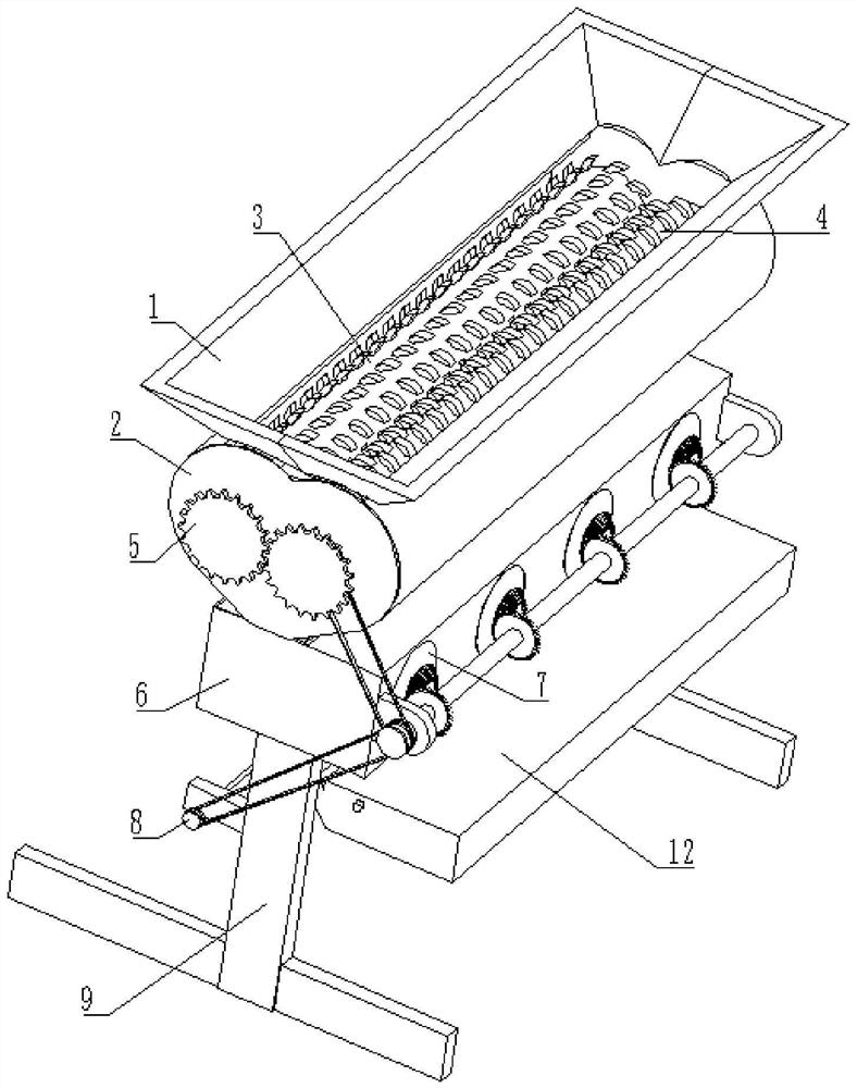
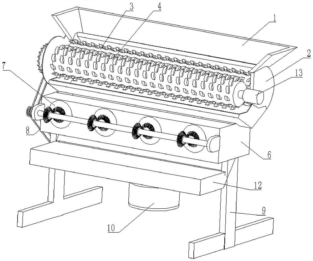
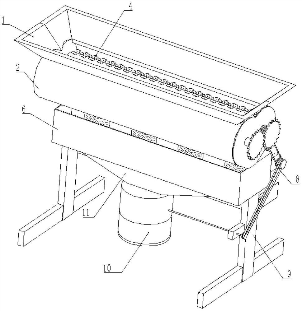
[0031] see Figure 1-6 , a medical waste cleaning treatment device, comprising a feed box 1, the bottom of the feed box 1 is welded with a treatment box 2, the inside of the treatment box 2 is respectively connected with a cutting roller 3 and a cutting roller 4, and the treatment box 2 The bottom of the frame 9 is fixedly connected with a separation box 6, the bottom of the separation box 6 is fixedly connected with a frame 9, the surface of the frame 9 is fixedly connected with a high temperature box 12, the surface of the frame 9 is provided with a transmission mechanism 8, and the inside of the separation box 6 is set There is a separation mechanism 7, the bottom of the separation box 6 is fixedly connected with a connecting pipe 11, the bottom of the connecting pipe 11 is provided with a disinfection mechanism 10, the right side of the processing box 2 is connected with a motor 13 by bolts, and the output end of the motor 13 is fixedly connected to the cutting machine. At...

Embodiment 2

[0039] see Figure 7-8 , on the basis of Embodiment 1, in the present embodiment, the transmission mechanism 8 includes a pulley one 81, the surface of the pulley one 81 is connected with the surface transmission of the double pulley 82 by a belt, and the surface of the double pulley 82 is connected by a belt and a pulley two 83 The surface transmission connection of the double belt pulley 82 is fixedly connected to the surface of the drive shaft 76, the axis of the belt pulley 81 is fixedly connected to the surface of the cutting roller 24, and the axis of the belt pulley 83 is fixedly connected to the transmission rod 84, the surface of transmission rod 84 is connected to the inside of frame 9 in rotation.

[0040] Through the connection and transmission of the pulley, the rotational force of the cutting roller is transmitted to the inside of the disinfection mechanism 10, reducing the use of the motor 13, thereby effectively reducing the cost and controlling the cost input....


PUM


Abstract

The invention relates to the technical field of waste treatment, and discloses a medical waste cleaning treatment device. The device comprises a feeding box, a treatment box is welded to the bottom of the feeding box, a separation box is fixedly connected to the bottom of the treatment box, a rack is fixedly connected to the bottom of the separation box, and a transmission mechanism is arranged on the surface of the rack. A separation mechanism is arranged in the separation box, a communicating pipe is fixedly connected to the bottom of the separation box, a disinfection mechanism is arranged at the bottom of the communicating pipe, and a motor is connected to the right side of the treatment box through bolts. According to the medical waste cleaning treatment device, rotation of fan blades can be controlled through rotation of a rotating shaft, high-strength air blowing can be generated through rotation of the fan blades to conduct air blowing classification on fallen fragments, and therefore the effect of automatic separation and classification of some needle cylinders can be achieved, medical staff do not need to manually remove the needle heads, the medical waste cleaning treatment device is convenient and fast, and the operation safety of whole medical staff is improved.

Description

technical field [0001] The invention relates to the technical field of waste treatment, in particular to a medical waste cleaning and treatment device. Background technique [0002] Medical waste refers to directly or indirectly infectious, toxic and other hazardous waste produced by medical and health institutions in medical treatment, prevention, health care and other related activities. Unlike domestic waste, medical waste contains a large number of bacteria, viruses and Chemical agents are highly infectious, biologically toxic and corrosive. Untreated or incompletely treated medical waste is randomly piled up, which can easily cause water, soil and air pollution, and cause direct or indirect harm to the human body. It may also be a source of epidemics. [0003] At present, in the waste disposal of some medical syringes or some infusion bags, many need to manually remove the needles on them before processing, which is very troublesome and has certain safety hazards. In t...

Claims


Application Information

Patent Timeline
IPC IPC(8): B02C18/08B02C18/14B02C18/24B02C23/20B07B4/02A61L11/00
CPCA61L11/00B02C18/0084B02C18/08B02C18/142B02C18/24B02C23/20B07B4/02
Inventor 不公告发明人
Owner 钟文理
Why Eureka
Try Eureka