Machining method for Y-shaped groove part of hydraulic support structural part

A hydraulic support and parts processing technology, applied in metal processing equipment, manufacturing tools, plasma welding equipment, etc., can solve the problems of long processing process, low efficiency, and low groove accuracy

Active Publication Date: 2021-04-09
ZHENGZHOU COAL MINING MACHINERY GRP
View PDF4 Cites 1 Cited by
  • Summary
  • Abstract
  • Description
  • Claims
  • Application Information

AI Technical Summary

Problems solved by technology

On the one hand, this processing method needs to use a variety of processing equipment, and the parts need to be transferred multiple times. The processing process is long and the efficiency is low. On the other hand, the parts need secondary positioning when cutting the groove, but the structural parts of the hydraulic support are mostly customized. The specifications are not uniform, so it is impossible to design reliable positioning molds, and the positioning accuracy can only be guaranteed by the skills and experience of workers, which leads to low groove accuracy and affects the quality of tailor welding of subsequent structural parts

Method used


Image

  • Machining method for Y-shaped groove part of hydraulic support structural part
  • Machining method for Y-shaped groove part of hydraulic support structural part
  • Machining method for Y-shaped groove part of hydraulic support structural part

Examples


Embodiment 1

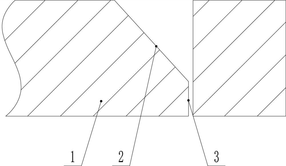
[0027] Such as Figure 2-5 As shown, a method for processing a Y-shaped groove part of a hydraulic support structure, when the thickness of the blunt side 3 is required to be greater than 2mm, includes the following steps:

[0028] (1) Place the steel plate to be cut flat on the workbench of the rotary plasma cutting machine;

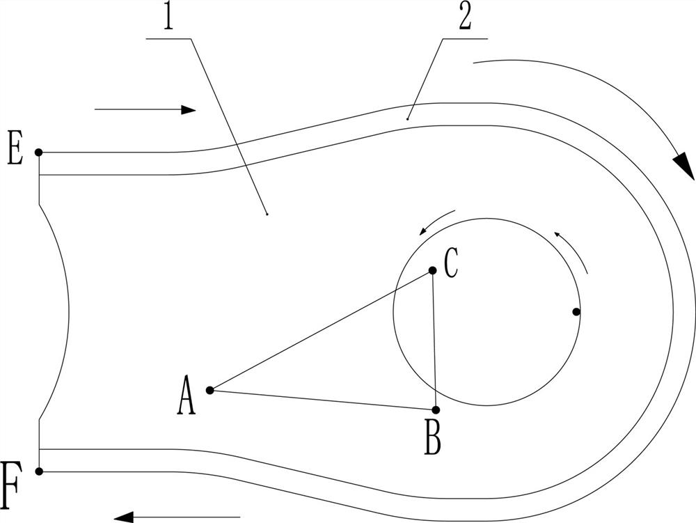
[0029] (2) Collect the spatial coordinates of three points on the top surface of the steel plate that are not on the same straight line; specifically, the tip of the torch 4 can be used to touch the three spatial points A, B, and C on the surface of the steel plate, and through contact sensing method to obtain the three-point space coordinates;

[0030] (3) Calculate the angle β between the steel plate and the horizontal plane according to the spatial coordinates of the three points;

[0031] (4) Adjust the angle of the torch 4 of the rotary plasma cutting machine so that the angle between it and the horizontal plane is β+90° (that is, it is perpendic...

Embodiment 2

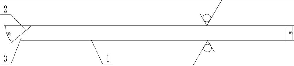
[0036] Such as Figure 6-9 As shown, a method for processing Y-shaped groove parts of a hydraulic support structure, when the thickness of the blunt side 3 is required to be 2mm, includes the following steps:

[0037] (1) Fix the steel plate to be cut on the worktable of the rotary plasma cutting machine;

[0038] (2) Collect the spatial coordinates of three points on the top surface of the steel plate that are not on the same straight line;

[0039] (3) Calculate the angle β between the steel plate and the horizontal plane according to the spatial coordinates of the three points;

[0040] (4) Set the angle of the target Y-shaped groove 2 as α, and use undercut cutting, that is, the opening side of the Y-shaped groove 2 faces away from the cutting torch 4, and adjust the angle between the cutting torch 4 and the horizontal plane to 90°-α- β, cut from one end of the cutting Y-shaped bevel edge of the target part 1 to the other end. During the cutting process, use the function...


PUM


Abstract

The invention provides a machining method for a Y-shaped groove part of a hydraulic support structural part. The machining method comprises the following steps that a, a steel plate to be cut is horizontally placed on a workbench of a rotary plasma cutting machine; b, space coordinates of three points, not located on the same straight line, of the top face of the steel plate are collected; c, an included angle beta between the steel plate and the horizontal plane is calculated according to the space coordinates of the three points; and d, the angle of a target Y-shaped groove is set to be alpha, the angle of a cutting gun of the rotary plasma cutting machine is adjusted to coincide with the inclination direction of the Y-shaped groove, and cutting is conducted from one end of the edge of the to-be-cut Y-shaped groove of the target part to the other end of the edge of the Y-shaped groove. The machining method for the Y-shaped groove part of the hydraulic support structural part has the advantages of being few in machining process, high in machining efficiency, high in slope precision and good in product quality.

Description

technical field [0001] The invention relates to a processing technology for a hydraulic support structural part, in particular to a processing method for a Y-shaped bevel part of a hydraulic support structural part. Background technique [0002] At present, the structural parts of hydraulic supports are generally tailor-welded from multiple parts cut from steel plates. The grooves need to be cut before the parts are tailor-welded. The quality of the grooves will eventually affect the strength of the structural parts. Most of the existing hydraulic support structural parts are Y-shaped groove parts, and the blunt edge size of the Y-shaped groove is generally not less than 2mm. The current processing flow is: first cut out the shape of the part with a flame or plasma cutting machine, During the cutting process, the parts will also have a certain amount of deformation, and then the deformation of the parts will be leveled by the flatbed machine, and finally the parts will be tr...

Claims


Application Information

Patent Timeline
Patent Type & Authority Applications(China)
IPC IPC(8): B23K10/00
CPCB23K10/00
Inventor 孟贺超李福永刘晟李臣阳汤利利银升超喻会新陈铭薛晓远
Owner ZHENGZHOU COAL MINING MACHINERY GRP
Why Eureka
Try Eureka