
Electron beam cutting equipment with placing table

A technology of cutting equipment and placing table, which is applied in the direction of electron beam welding equipment, welding equipment, metal processing equipment, etc., can solve the problems of inconvenient storage, large space occupied by the placing table, lack of space, etc., and achieve the effect of improving the storage function

Active Publication Date: 2021-04-09
北京中科华正电气有限公司
View PDF10 Cites 3 Cited by
  • Summary
  • Abstract
  • Description
  • Claims
  • Application Information

AI Technical Summary

Problems solved by technology

[0004] 1. Comparative document CN 110367759 A discloses a negative pressure fixed computer retail customer experience placement platform, "including partition boards, computer fixing platforms, placement platform bases, advertising columns, support columns, and the placement platform base is close to the ground. Together, the supporting column and the base of the placing table are inserted together, and the computer fixing table is fixed above the supporting column through bolts. The customer experience placing table for computer retail is installed with a negative pressure fixing structure, and the bottom of the computer is fixed to the place by the suction generated by the negative pressure. Therefore, even after the salesperson uses a wet towel to remove the dust on the experience placement platform, there will be no situation where the computer slips sideways during the operation of the user and the computer falls from the placement platform, effectively improving Improve the experience of customers, and reduce the risk of damage to the computer", but the table takes up a lot of space when it is not in use, and it is inconvenient to store;
[0005] 2. The comparative document CN108195328A discloses an adjustable inspection fixture placement table with multiple adjustment methods, "including four sleeves, a bottom plate, a lifting assembly, a rotating assembly, an inclined assembly, and a inspection fixture placement table. The bottom plate is a rectangular plate body , the bottom plate is set horizontally, the four corners of the bottom plate are respectively connected with a sleeve, the upper surface of the bottom plate is provided with a lifting assembly, the upper surface of the lifting assembly is provided with a rotating assembly, the upper surface of the rotating assembly is provided with a tilting assembly, and the upper surface of the tilting assembly is provided with a detection "fixed components", but there is no corresponding device to clamp and fix the processing objects of different shapes, resulting in the processing objects of the device being limited by the appearance
[0006] 3. The comparative document CN106826954A discloses an intelligent cutting device based on the Internet of Things, "including a base, a cutting mechanism, a fixing mechanism and a central control mechanism. The cutting mechanism includes two columns, a cutting blade and a driving assembly. The driving assembly includes a transmission rod, The fixed block, the guide rod and the electromagnetic coil, the fixed mechanism includes a fixed component, and the fixed unit includes a positioning rod, a positioning sleeve and a fixing ring. In this intelligent cutting device based on the Internet of Things, the electromagnetic coil starts to be energized at a high speed, and generates a strong suction force on the magnet , so that the transmission rod controls the cutting blade to cut horizontally, so that each plastic tube is cut one by one, which improves the efficiency of the cutting equipment; not only that, but also controls the positioning sleeve to move on the positioning rod to realize the movement of the fixed ring. The fixing ring will form a circular ring with a set diameter, and the plastic pipe of this diameter is fixed, which improves the practicability of the cutting equipment", but lacks a corresponding exhaust device to ensure that the device can flexibly switch between vacuum and non-gas. Vacuum state brings inconvenience to the use of the device

Method used


Image

  • Electron beam cutting equipment with placing table
  • Electron beam cutting equipment with placing table
  • Electron beam cutting equipment with placing table

Examples


Embodiment Construction

[0036] The following will clearly and completely describe the technical solutions in the embodiments of the present invention with reference to the accompanying drawings in the embodiments of the present invention. Obviously, the described embodiments are only some, not all, embodiments of the present invention. Based on the embodiments of the present invention, all other embodiments obtained by persons of ordinary skill in the art without making creative efforts belong to the protection scope of the present invention.

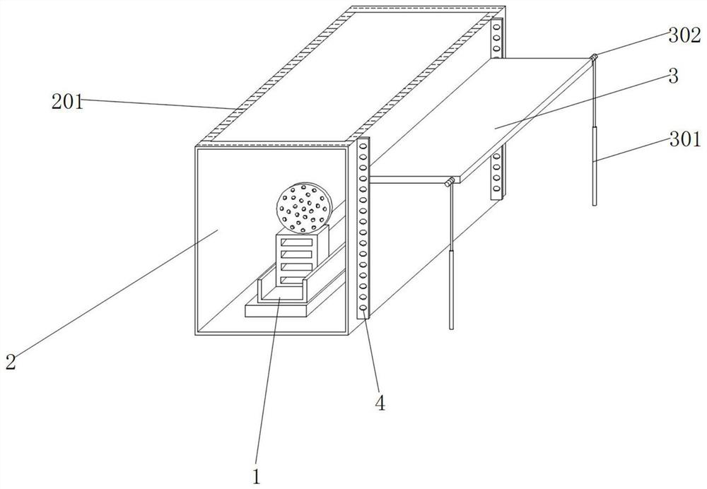
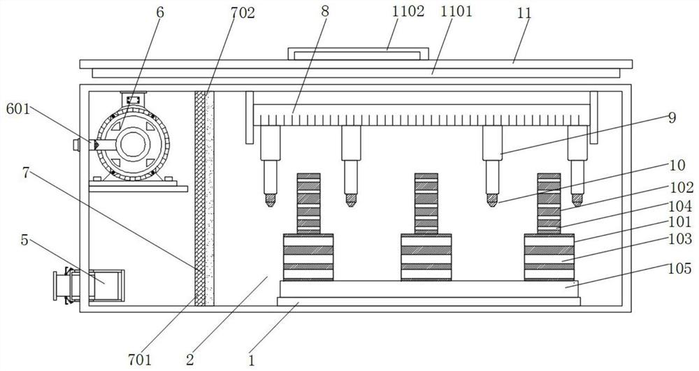
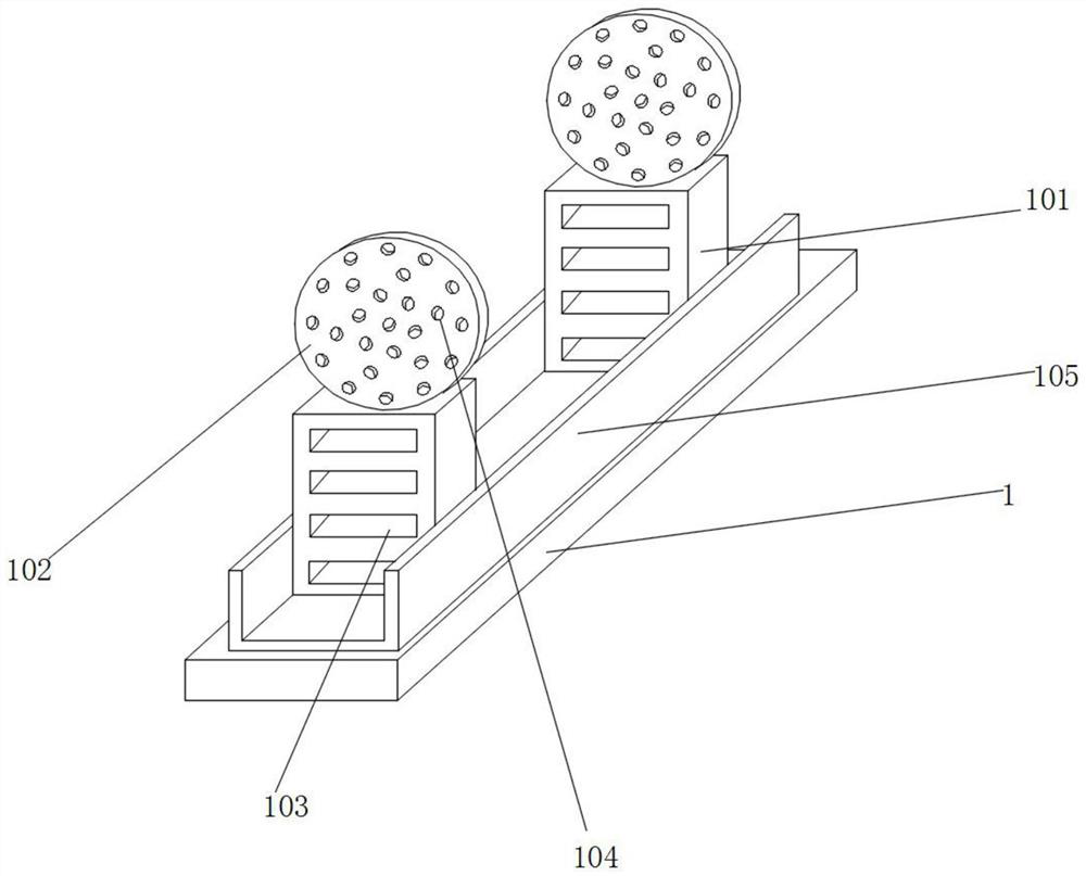
[0037] see Figure 1-9 , an embodiment provided by the present invention: an electron beam cutting device with a placement table, including a horizontal plate 1, a cutting box 2, a placement table 3, a support plate 4, an exhaust pipe 5, a vacuum pump 6 and an embedded Combined column 9, the inner bottom of cutting box 2 is equipped with horizontal plate 1, and cutting box 2 can provide operating space for this device to carry out electron beam cutting operati...


PUM


Abstract

The invention discloses electron beam cutting equipment with a placing table. The electron beam cutting equipment comprises a cutting box, the placing table, an exhaust pipeline, a vacuum air pump and an embedding column, wherein a transverse plate is arranged at the bottom of the interior of the cutting box; an interlayer is arranged in the cutting box, and a clamping groove is formed in the bottom of the interlayer through a longitudinal plate; the embedding column is slidably arranged in the clamping groove, and an electronic gun is arranged at the bottom of the embedding column; a net rack is arranged at the bottom of the interlayer and located behind the transverse plate; the vacuum air pump is fixed to the rear wall of the cutting box, a box cover is slidably arranged in the interlayer, and the exhaust pipeline is arranged on the rear wall of the cutting box; two sets of supporting plates arranged front and back are arranged on the outer wall of one side of the cutting box; and the placing table is arranged on the surfaces of one sides of the supporting plates. By arranging a series of assemblies, the placing table can be flexibly stored when the equipment is used, and thus unnecessary space occupation is reduced.

Description

technical field [0001] The invention relates to the technical field of cutting equipment, in particular to an electron beam cutting equipment with a placing table. Background technique [0002] The electron beam can be focused into a very small spot, so its output power density per unit time is high, and it can cut and process high melting point and difficult-to-process materials such as tungsten, stainless steel, diamond, crystal, glass, ceramics, etc., and because of its The electron beam emitted by the electron gun is used for the cutting operation. Compared with the traditional knife cutting, the electron beam cutting does not need to achieve mechanical contact with the cutting object, there is no mechanical wear, and the service life of the tool is longer. Therefore, the electron beam cutting equipment is used in precision machining. It has a good application prospect. [0003] The defect that existing e-book cutting equipment exists is: [0004] 1. Comparative docume...

Claims


Application Information

Patent Timeline
IPC IPC(8): B23K15/00B23K15/06B23K15/08
CPCB23K15/08B23K15/00B23K15/06
Inventor 李大平
Owner 北京中科华正电气有限公司
Learn More