Automatic glass film pasting device

A glass film, sliding plate technology, used in lamination devices, chemical instruments and methods, lamination auxiliary operations, etc.

Inactive Publication Date: 2021-04-09
芜湖起岩智能装备有限公司
View PDF0 Cites 0 Cited by
  • Summary
  • Abstract
  • Description
  • Claims
  • Application Information

AI Technical Summary

Problems solved by technology

[0004] In view of the existing problem that there is no special auxiliary tool in the process of glass film sticking, many operators are required, the operation is difficult, and a large number of air bubbles are prone to appear after the glass film is pasted, the present invention provides an automatic glass film sticking device, the film sticking device Including a frame, a pressure component and a fixing component, the combination of the components can effectively solve the problems raised in the background technology

Method used


Image

  • Automatic glass film pasting device
  • Automatic glass film pasting device
  • Automatic glass film pasting device

Examples


Embodiment 1

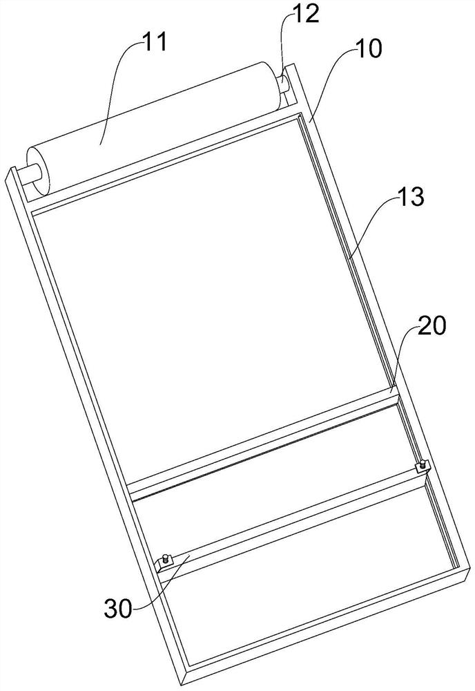
[0031] Such as Figure 1-5 As shown, it is a schematic structural view of an automatic glass film sticking device in a preferred embodiment of the present invention. The window frame 10 in this embodiment includes a roller 11, a roller 12, and a groove 13. The roller 11 and The roller 12 is rotatably connected, the roller 12 is rotatably connected to the groove 13, the groove 13 is symmetrically distributed with respect to the vertical center line of the window frame 10, and the groove 13 is slidably connected to the pressure assembly 20, The fixing assembly 30 is connected to the groove 13, and the pressure assembly 20 and the fixing assembly 30 are distributed in parallel with respect to the window frame 10;

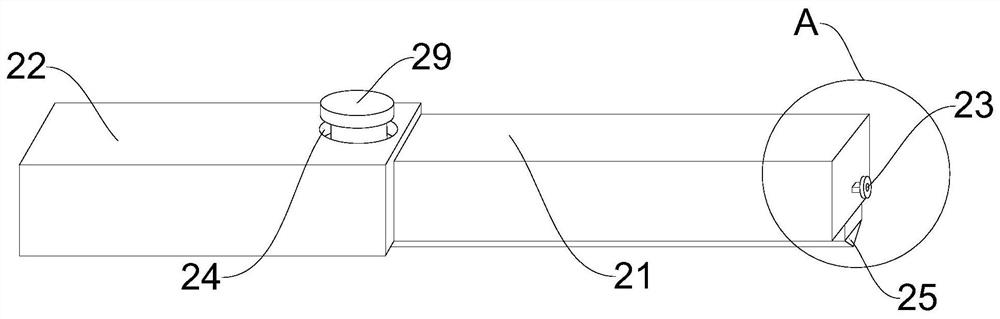
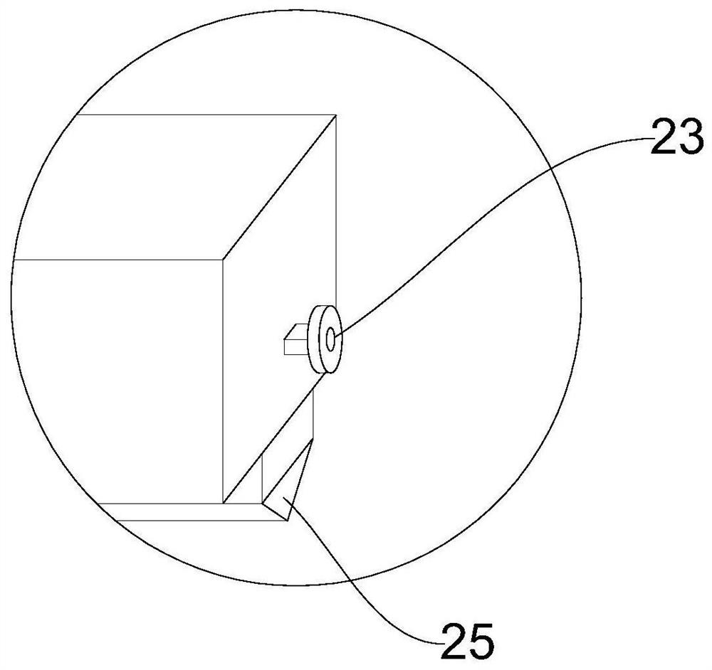
[0032] The pressure assembly 20 includes a sliding plate 21, a fixed plate 22 and a pulley 23, the sliding plate 21 is slidably connected with the fixed plate 22, the fixed plate 22 is a hollow structure, and a chute 26 is provided on the inner surface, so The two end...

Embodiment 2

[0036] Such as Image 6 with Figure 7 As shown, it is a structural schematic diagram of an automatic glass film sticking device in another preferred embodiment of the present invention. The fixing assembly 30 includes a folding plate 31 and a bottom plate 35, and the two ends of the upper end surface of the bottom plate 35 are provided with folding plate 31, the folded plate 31 is connected with the second fixed opening 32, the right side of the bottom plate 35 is provided with a pulley 34, the pulley 34 is slidingly connected with the groove 13, and the screw 33 connected inside the second fixed port 32;

[0037] On the basis of Embodiment 1, in the process of glass film sticking, the glass film is placed on the two ends of the fixing assembly 30, and the screw 33 is turned to make it move downwards in a spiral, so as to fix the glass film on the top and pull the fixing assembly 30 to the tail end of the window frame 10, thereby solving the problem that two operators are r...


PUM


Abstract

The invention discloses an automatic glass film pasting device, belonging to the technical field of glass installation. The automatic glass film pasting device comprises a frame, a pressure assembly and a fixing assembly, wherein the frame comprises a roller, a rolling shaft and a groove; the pressure assembly comprises a sliding plate, a fixing plate and a pulley; the sliding plate is in sliding connection with the fixing plate; the fixing plate is of a hollow structure; the fixing assembly comprises folding plates and a bottom plate; the folding plates are arranged at the two ends of the upper end face of the bottom plate; and the pressure assembly is a telescopic device. After the fixing assembly fixes a glass film, the pressure assembly can flatten and extrude the glass film, and the problem that a large number of bubbles exist after a glass film is formed due to errors of an operator in a manual film pasting process is solved; and meanwhile, the device is easy to operate, glass film pasting can be completed by one person independently, and technological process is simplified.

Description

technical field [0001] The invention belongs to the technical field of glass installation, and in particular relates to an automatic glass film sticking device. Background technique [0002] As an important building material, glass is widely used in daily life. As an additional product of glass, glass film has become more important. Glass film can prevent direct sunlight from entering the room in summer and reduce heat loss in winter. When the glass is broken, the glass film can also tightly adhere to the glass fragments to keep it in its original shape without splashing or deforming; [0003] The existing glass film sticking method does not have special auxiliary tools and relies entirely on manual operation. Often due to operator errors, there are a lot of air bubbles in the pasted glass film, which not only reduces the beauty of the glass, but also greatly reduces its practicability. The area of ​​the glass is generally large. In order to ensure the quality of the film, ...

Claims


Application Information

Patent Timeline
IPC IPC(8): B32B37/10B32B37/00B32B38/18
CPCB32B37/003B32B37/10B32B38/1808
Inventor 姚铁军张传月麦文杰项小敏
Owner 芜湖起岩智能装备有限公司
Why Eureka
Try Eureka