
Waste heat recovery system for large calcium carbide smelting

A waste heat recovery system and calcium carbide technology, applied in the field of waste heat recovery equipment, can solve the problems affecting the waste heat recovery of calcium carbide liquid

Active Publication Date: 2021-04-09
重庆岩昱节能科技有限公司
View PDF11 Cites 0 Cited by
  • Summary
  • Abstract
  • Description
  • Claims
  • Application Information

AI Technical Summary

Problems solved by technology

[0005] The present invention provides a waste heat recovery system for large-scale calcium carbide smelting to solve the problem of using trolleys for transport in the prior art. Due to the fast solidification speed of calcium carbide liquid, a layer of calcium carbide layer will be formed on the surface of the calcium carbide liquid in the trolley. Thus affecting the waste heat recovery of calcium carbide liquid

Method used


Image

  • Waste heat recovery system for large calcium carbide smelting
  • Waste heat recovery system for large calcium carbide smelting
  • Waste heat recovery system for large calcium carbide smelting

Examples


Embodiment 1

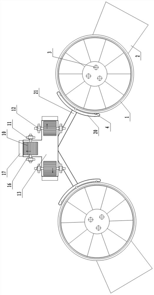
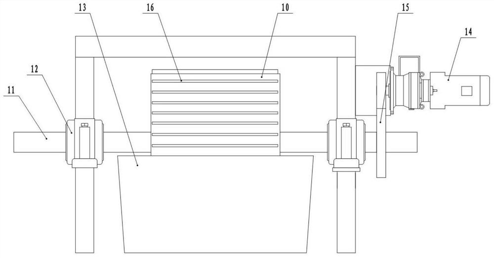
[0037] Basic as attached figure 1 , figure 2 , image 3 and Figure 4 Shown: The waste heat recovery system for large-scale calcium carbide smelting is located between multiple calcium carbide smelting furnaces. In this embodiment, there are two calcium carbide smelting furnaces. The calcium carbide smelting furnace includes a furnace body 1, a feed port 2, and an electrode 3 and three discharge ports 4; in this embodiment, the waste heat recovery system includes a frame, a diversion assembly, a heat-absorbing assembly, a slag cylinder 13, a granulator, a lifting conveyor, a secondary heat exchange system, and a belt conveyor, wherein The secondary heat exchange system is a rotary kiln.

[0038]The diversion assembly is fixed on the frame, and there are two diversion assemblies, which are arranged symmetrically on both sides of the slag cylinder 13. The diversion assembly includes arc-shaped grooves 20 and diversion grooves 21, wherein the arc-shaped grooves 20 are located...

Embodiment 2

[0047] Basic as attached Figure 5 As shown, the difference with Embodiment 1 is that in this embodiment, the bar 16 is arc-shaped, that is, the plane where the two ends of the bar 16 is located does not coincide with the plane where the middle part is located, and the direction of the arc-shaped concave surface of each bar 16 is in line with the The direction of rotation of the rollers 10 is the same; the reason for this arrangement is that when the heat-absorbing head is working, the temperature of the roller 10 near the cooling medium input end is lower than that of the cooling medium output end, so the calcium carbide solution attached to the cooling medium near the input end is cooled faster. Slightly higher than that attached to the other end, so the calcium carbide solution has a faster solidification speed on the outer wall of the roller 10 at the input end, and the thickness of the solidified calcium carbide layer is greater than other parts at the same time. If the so...

Embodiment 3

[0049] Basic as attached Figure 6 and Figure 7 As shown, the difference from Embodiment 1 is that in this embodiment, one or more scraping slits 18 are provided on each bar 16, and there are two scraping slits 18 in this embodiment, and the width of the scraping slits 18 is less than 10mm, the adjacent scraping seam 18 on the upper and lower adjacent bar 16 is located on the same circumferential line of the roller 10, and a scraper 19 is fixed on the side of the slag receiving hopper 17 close to the slag cylinder 13, and the number of scrapers 19 is the same as that of the bar 16. The scraping slits 18 are the same, that is, there are two scrapers 19 in this embodiment, and the top of the scraper 19 is close to the outer wall of the roller 10 and can pass through the scraping slits 18, so that when the solidified strip calcium carbide layer on the roller 10 When rotating to one side close to the slag receiving hopper 17, the strip-shaped calcium carbide layer is cut off by ...


PUM


Abstract

The invention relates to the technical field of waste heat recovery equipment, and particularly discloses a waste heat recovery system for large calcium carbide smelting. The system is connected with discharge ports of a plurality of calcium carbide smelting furnaces, and comprises a rack, a heat absorption assembly, a slag cylinder, a granulator, a lifting conveyor, a secondary heat exchange system and a belt conveyor. The heat absorption assembly comprises a heat absorption head, the heat absorption head comprises a hollow roller and two hollow shafts, the two hollow shafts are rotatably connected to the rack, the slag cylinder is arranged below the roller, the rack is further provided with a plurality of flow guide assemblies, each flow guide assembly comprises an arc-shaped groove and a flow guide groove, the arc-shaped grooves are located below a plurality of discharge ports of one single calcium carbide smelting furnace, and the flow guide grooves are connected with the arc-shaped grooves and the slag cylinder. A plurality of barrier strips are arranged on the roller, and a slag receiving hopper is further arranged at the top of the granulator. According to the invention, the mode of transferring by using a trolley in the prior art is abandoned, and the problem that the calcium carbide liquid in the trolley can quickly form a calcium carbide layer on the surface due to higher solidification speed of the calcium carbide liquid, so that the waste heat recovery of the calcium carbide liquid is influenced is solved.

Description

technical field [0001] The invention relates to the technical field of waste heat recovery equipment, in particular to a waste heat recovery system for large calcium carbide smelting. Background technique [0002] In the production process of calcium carbide, the molten calcium carbide liquid discharged from the smelting furnace needs to be cooled before being crushed. At present, the traditional high-temperature calcium carbide liquid cooling methods include natural cooling, air cooling, etc., but the above methods have the following problems: (1) Due to the high temperature of the high-temperature calcium carbide solution, the required cooling time is longer; (2) The high-temperature calcium carbide solution contains a large amount of waste heat, and the above-mentioned method cannot utilize the waste heat, resulting in a waste of energy. [0003] Based on such problems, our company has carried out a series of technical research and development, and developed a set of wast...

Claims


Application Information

Patent Timeline
Patent Type & Authority Applications(China)
IPC IPC(8): C01B32/942F27D17/00B02C19/00
CPCC01B32/942F27D17/004B02C19/0056Y02P10/25Y02P20/10Y02P20/129
Inventor 杨帆何名正
Owner 重庆岩昱节能科技有限公司
Learn More