Waste heat recovery system for smelting of calcium carbide
A waste heat recovery system, calcium carbide technology, applied in waste heat treatment, electric charge manipulation, treatment of discharged materials, etc., can solve problems affecting the recovery of calcium carbide liquid waste heat, etc.
- Summary
- Abstract
- Description
- Claims
- Application Information
AI Technical Summary
Problems solved by technology
Method used
Image
Examples
Embodiment 1
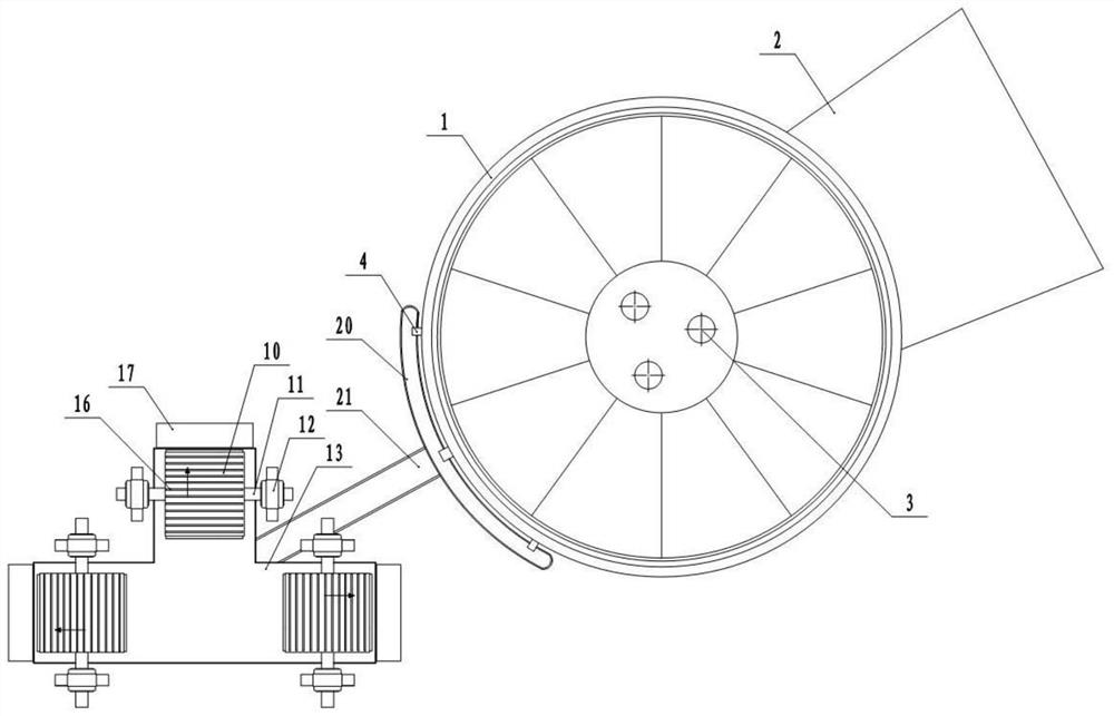
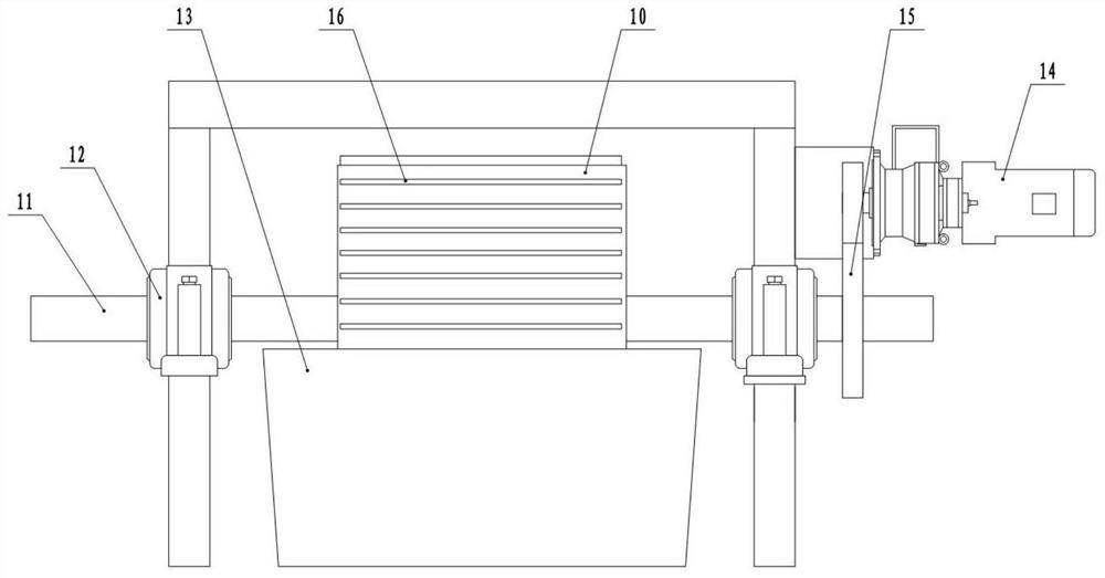
[0036] Basic as attached figure 1 , figure 2 , image 3 and Figure 4 Shown: The waste heat recovery system for calcium carbide smelting is installed close to the calcium carbide smelting furnace, wherein the calcium carbide smelting furnace includes a furnace body 1, a feed port 2, an electrode 3 and three discharge ports 4; the waste heat recovery system in this embodiment includes Frame, diversion components, heat-absorbing components, slag tank 13, granulator, lifting conveyor, secondary heat exchange system and belt conveyor, wherein the secondary heat exchange system is a rotary kiln.
[0037] The diversion assembly is fixed on the frame and includes an arc-shaped groove 20 and a diversion groove 21, wherein the arc-shaped groove 20 is located below the three discharge ports 4, and the calcium carbide liquid discharged from the three discharge ports 4 enters the arc-shaped In the groove 20, the diversion groove 21 connects the arc groove 20 and the slag cylinder 13, ...
Embodiment 2
[0046] Basic as attached Figure 5 As shown, the difference with Embodiment 1 is that in this embodiment, the bar 16 is arc-shaped, that is, the plane where the two ends of the bar 16 is located does not coincide with the plane where the middle part is located, and the direction of the arc-shaped concave surface of each bar 16 is in line with the The direction of rotation of the rollers 10 is the same; the reason for this arrangement is that when the heat-absorbing head is working, the temperature of the roller 10 near the cooling medium input end is lower than that of the cooling medium output end, so the calcium carbide solution attached to the cooling medium near the input end is cooled faster. Slightly higher than that attached to the other end, so the calcium carbide solution has a faster solidification speed on the outer wall of the roller 10 at the input end, and the thickness of the solidified calcium carbide layer is greater than other parts at the same time. If the so...
Embodiment 3
[0048] Basic as attached Figure 6 and Figure 7 As shown, the difference from Embodiment 1 is that in this embodiment, one or more scraping slits 18 are provided on each bar 16, and there are two scraping slits 18 in this embodiment, and the width of the scraping slits 18 is less than 10mm, the adjacent scraping seam 18 on the upper and lower adjacent bar 16 is located on the same circumferential line of the roller 10, and a scraper 19 is fixed on the side of the slag receiving hopper 17 close to the slag cylinder 13, and the number of scrapers 19 is the same as that of the bar 16. The scraping slits 18 are the same, that is, there are two scrapers 19 in this embodiment, and the top of the scraper 19 is close to the outer wall of the roller 10 and can pass through the scraping slits 18, so that when the solidified strip calcium carbide layer on the roller 10 When rotating to one side close to the slag receiving hopper 17, the strip-shaped calcium carbide layer is cut off by ...
PUM
 Abstract
Description
Claims
Application Information
 - R&D
- Intellectual Property
- Life Sciences
- Materials
- Tech Scout
- Unparalleled Data Quality
- Higher Quality Content
- 60% Fewer Hallucinations
Browse by: Latest US Patents, China's latest patents, Technical Efficacy Thesaurus, Application Domain, Technology Topic, Popular Technical Reports.
© 2025 PatSnap. All rights reserved.Legal|Privacy policy|Modern Slavery Act Transparency Statement|Sitemap|About US| Contact US: help@patsnap.com


