Electroplating equipment with impurity removal function

A technology of electroplating equipment and functions, applied in the field of electroplating equipment with impurity removal function, can solve the problems of prolonging the time for the formation of the coating layer on the surface of the workpiece, reducing the reliability of electroplating equipment, reducing the quality of electroplating finished products, etc. High practicability and effect of preventing influence

Inactive Publication Date: 2021-04-09
南京鸿音工程技术有限公司
View PDF3 Cites 0 Cited by
  • Summary
  • Abstract
  • Description
  • Claims
  • Application Information

AI Technical Summary

Problems solved by technology

[0003] When the existing electroplating equipment is working, more impurities and residues will be produced in the plating solution. When the plating solution contains too many impurities, it will affect the electroplating work and reduce the quality of the electroplating finished product. Not only that, the existing When the electroplating equipment is working, due to the slow flow of the plating solution inside the main body, the time for forming the coating on the surface of the workpiece is prolonged, thereby reducing the efficiency of electroplating and reducing the reliability of the existing electroplating equipment.

Method used


Image

  • Electroplating equipment with impurity removal function
  • Electroplating equipment with impurity removal function
  • Electroplating equipment with impurity removal function

Examples


Embodiment Construction

[0028] The present invention is described in further detail now in conjunction with accompanying drawing. These drawings are all simplified schematic diagrams, which only illustrate the basic structure of the present invention in a schematic manner, so they only show the configurations related to the present invention.

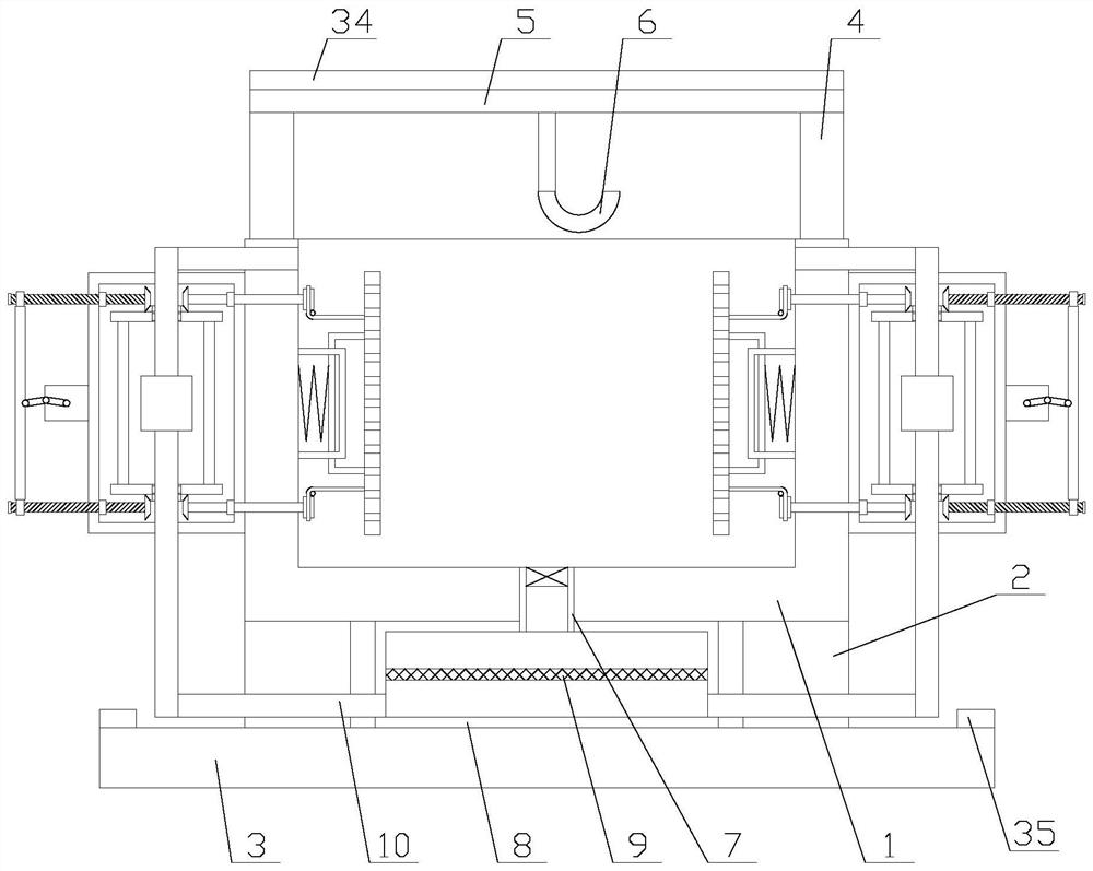
[0029] Such as figure 1 As shown, a kind of electroplating equipment with impurity removal function includes a base plate 3, a main body 1, a top plate 5, a hook 6, two lifting devices 4 and four support blocks 2, and the four corners below the main body 1 pass through four A supporting block 2 is fixed on the top of the bottom plate 3, two lifting devices 4 are respectively arranged on both sides above the main body 1, the two sides of the top plate 5 are respectively connected with the two lifting devices 4, and the hook 6 is fixed on the top plate 5, the bottom plate 3 is provided with a PLC, and also includes an impurity removal mechanism and two stirring...


PUM


Abstract

The invention relates to electroplating equipment with an impurity removal function. The electroplating equipment comprises a bottom plate, a main body, a top plate, a hook, two lifting devices, four support blocks, an impurity removal mechanism and two stirring mechanisms, wherein the impurity removal mechanism comprises an impurity removal box, a filter screen, a connecting pipe and two circulating assemblies, the stirring mechanism comprises a moving plate, a first limiting rod, a second limiting rod, a first spring and two transmission assemblies. According to the electroplating equipment with the impurity removal function, through the impurity removal mechanism, the function of removing impurities from a plating solution is achieved, the impurity content of the plating solution is reduced, the influence on the electroplating quality is avoided, and therefore the reliability of the equipment is improved; and through the stirring mechanism, the function of stirring the plating solution in the main body is realized, and the flowing speed of the plating solution is increased, so that the speed of covering a workpiece with the plating solution can be increased, the electroplating working efficiency is improved, the reliability of equipment is improved, cations in the plating solution are uniformly distributed, and the electroplating quality is improved.

Description

technical field [0001] The invention relates to the field of hardware equipment processing, in particular to an electroplating equipment with the function of removing impurities. Background technique [0002] Electroplating is the process of plating a thin layer of other metals or alloys on the surface of certain metals using the principle of electrolysis. It is a process of using electrolysis to attach a layer of metal film to the surface of metal or other material parts to prevent metal oxidation ( Such as rust), improve wear resistance, conductivity, reflectivity, corrosion resistance (copper sulfate, etc.) and enhance the appearance, etc. The outer layer of many coins is also electroplated. [0003] When the existing electroplating equipment is working, more impurities and residues will be produced in the plating solution. When the plating solution contains too many impurities, it will affect the electroplating work and reduce the quality of the electroplating finished p...

Claims


Application Information

Patent Timeline
Patent Type & Authority Applications(China)
IPC IPC(8): C25D21/02C25D21/06C25D21/10C25D17/00
CPCC25D17/00C25D21/02C25D21/06C25D21/10
Inventor 解帅
Owner 南京鸿音工程技术有限公司
Why Eureka
Try Eureka