Supercharge Your Innovation With Domain-Expert AI Agents!

Motor rotor structure

A technology of motor rotor and motor shaft, which is applied in the manufacture of motor generators, stator/rotor body, magnetic circuit shape/style/structure, etc., which can solve the force that affects the normal operation and use of the whole machine, and the axial force Small size, large amount of elastic rubber used, etc., to achieve the effect of improving life, concentricity and service life

Pending Publication Date: 2021-04-09
JIANGSUSNGQI GROUP
View PDF0 Cites 2 Cited by
  • Summary
  • Abstract
  • Description
  • Claims
  • Application Information

AI Technical Summary

Problems solved by technology

[0003] 1. The inner and outer rotors are only fixed by rubber, and the axial force can be small; the amount of elastic rubber used is large;
[0004] 2. Two times of injection molding and two times of mold loading are prone to deviation, poor injection concentricity, and poor dynamic balance of the product;
[0005] 3. The motor has large vibration and poor noise, which affects the normal operation and use of the whole machine

Method used


Image

  • Motor rotor structure
  • Motor rotor structure
  • Motor rotor structure

Examples


Embodiment

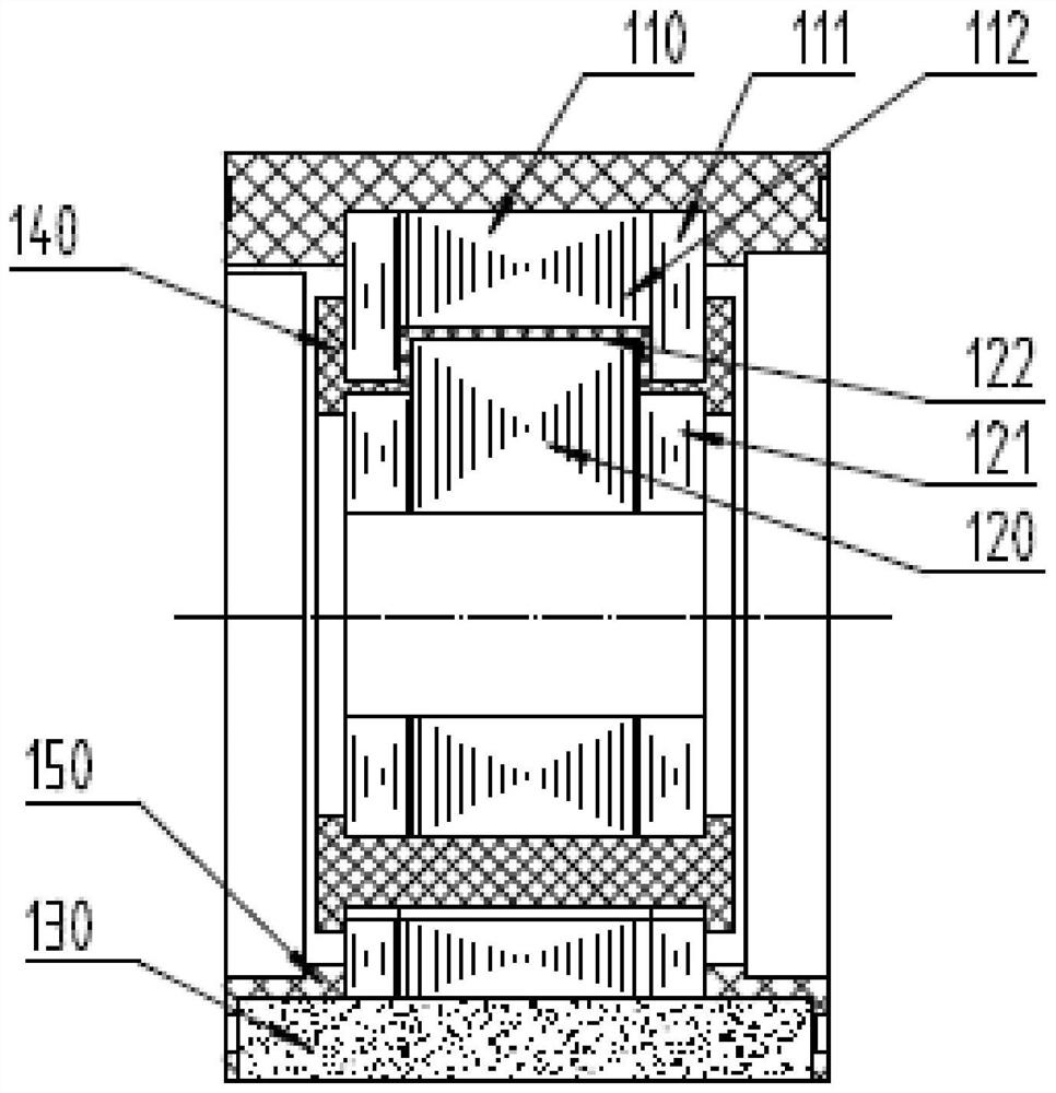
[0037] A motor rotor structure, including a motor shaft, also includes:

[0038] The inner rotor core 120 is sleeved on the outer periphery of the motor shaft;

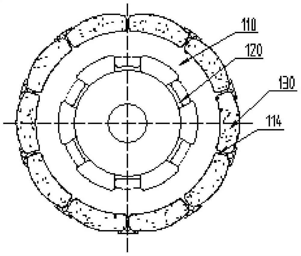
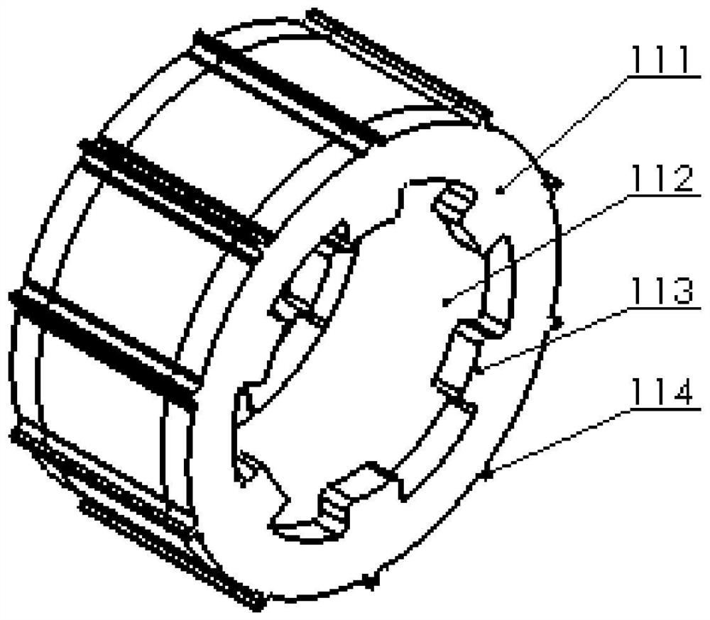
[0039] The outer rotor core 110 is sleeved on the outer periphery of the inner rotor core 120;

[0040] There is a gap between the inner rotor core 120 and the outer rotor core 110, and the gap is filled with injection rubber 140 for connecting and forming the inner rotor core 120 and the outer rotor core 110;

[0041] The limiting ribs 114 are arranged on the outer surface of the outer rotor core 110, the outer surface of the outer rotor core 110 is provided with a number of limiting ribs 114, and the plurality of limiting ribs 114 are evenly distributed on the outer rotor core the outer surface of 110;

[0042] The permanent magnet 130 is installed between the adjacent limiting ribs 114 by engaging.

[0043] The contact position between the limiting rib 114 and the permanent magnet 130 is covered with injection m...


PUM


Abstract

The invention discloses a motor rotor structure which comprises a motor rotating shaft and further comprises an inner rotor iron core arranged on the periphery of the motor rotating shaft in a sleeving mode; an outer rotor iron core which sleeves the periphery of the inner rotor iron core; a gap which is formed between the inner rotor iron core and the outer rotor iron core and is filled with injection molding rubber for the connection and molding of the inner rotor iron core and the outer rotor iron core; limiting ribs which are circumferentially and uniformly arranged on the outer surface of the outer rotor iron core; and permanent magnets which are installed between the adjacent limiting ribs in a clamped mode. The outer rotor iron core and the inner rotor iron core are connected and formed through the injection molding rubber, the connection firmness of the outer rotor iron core and the inner rotor iron core can be improved, the service life is prolonged, the inner iron core rotor and the outer iron core rotor are isolated through the rubber, the internal electric corrosion of the motor bearing can be effectively reduced, and the service life of the motor bearing is prolonged; meanwhile, the vibration of a motor and load noise of the motor are reduced.

Description

technical field [0001] The invention relates to the technical field of motor rotors, in particular to a motor rotor structure. Background technique [0002] The rubber shock-absorbing rotor is a new rotor structure. The outer magnetic tile is fixed with PBT material, and the rubber elastic material is used between the inner and outer rotors to provide shock absorption. In the prior art, the bosses of the outer rotor and the inner rotor are generally spaced apart. The production method is to first complete the injection molding of the outer PBT material, and then perform the injection molding of the rubber elastic material inside. The original design and processing methods tend to have the following disadvantages or shortcomings: [0003] 1. The inner and outer rotors are only fixed by rubber, and the axial force can be small; the amount of elastic rubber used is large; [0004] 2. Two times of injection molding and two times of mold loading are prone to deviation, poor inj...

Claims


Application Information

Patent Timeline
IPC IPC(8): H02K1/27H02K1/28H02K15/03
CPCH02K1/274H02K1/28H02K15/03
Inventor 印光宇吴兴徐兆明
Owner JIANGSUSNGQI GROUP
Features
  • R&D
  • Intellectual Property
  • Life Sciences
  • Materials
  • Tech Scout
  • Unparalleled Data Quality
  • Higher Quality Content
  • 60% Fewer Hallucinations
Learn More