Speed control one-way valve

A technology of one-way valve and speed control valve, which is applied in the direction of valve device, valve details, valve housing structure, etc., to reduce complexity and realize the effect of direct drive and direct control

Active Publication Date: 2021-04-13
ANHUI UNIVERSITY OF TECHNOLOGY
View PDF6 Cites 0 Cited by
  • Summary
  • Abstract
  • Description
  • Claims
  • Application Information

AI Technical Summary

Problems solved by technology

[0006] Aiming at the deficiency that the check valve in the prior art cannot realize automatic shut-off through the reverse fluid speed control valve, the present invention provides a speed control check valve , not only can realize the forward and reverse flow control states of the fluid in the speed control check valve, but also the reverse closing action of the valve is determined by the reverse flow velocity of the fluid

Method used


Image

  • Speed control one-way valve
  • Speed control one-way valve
  • Speed control one-way valve

Examples


Embodiment 1

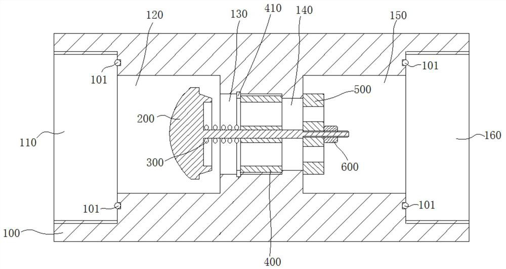
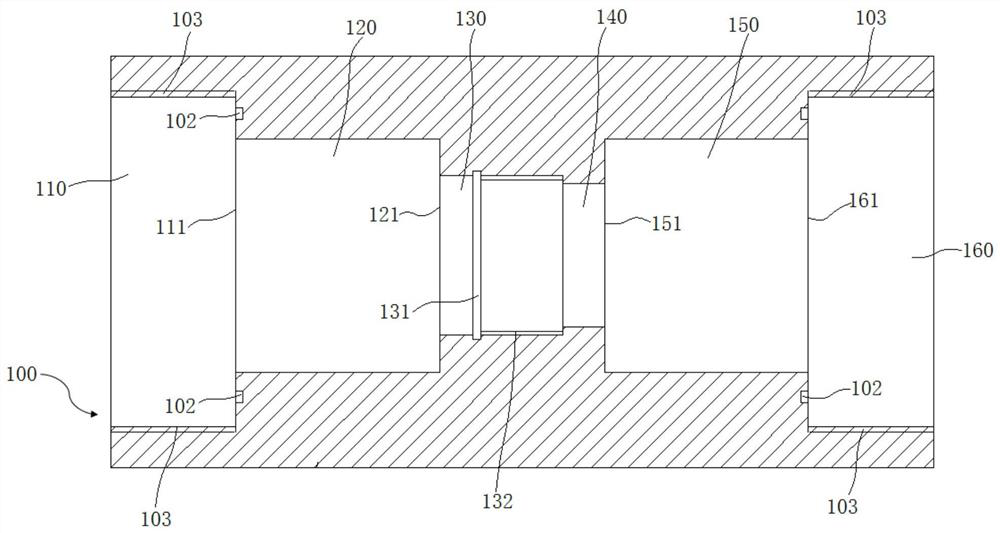
[0041] A common application scenario in the field of fluid control is that in the hydraulic vertical lifting system, the hydraulic cylinder drives the moving weight to move up and down, and the speed of rising and falling is regulated by the flow control system. Once the hydraulic control system fails, the weight will accelerate vertically out of control In the event of a fall, the oil circuit should be closed in time through the one-way valve to achieve a safe speed limit. Therefore, there is a need for a speed control check valve. The fluid can make the fluid flow smoothly in the forward and reverse directions within a certain flow rate range. The reverse shutdown of the road. Using the speed control check valve of this embodiment can meet the requirements in the above application scenarios. Specifically, such as Figure 1-Figure 8 As shown, a speed control check valve in this embodiment includes a valve body 100 and a speed control spool assembly. The two ends of the valv...

Embodiment 2

[0051] A kind of speed control check valve of this embodiment, the basic structure is consistent with embodiment 1, further, as Figure 5 As shown, the diameter of the outer circle of the outer edge of the throttle hole 502 in this embodiment is d, and the outer diameter d is smaller than the diameter of the flow guide cavity 140 , and the diameter of the flow guide cavity 140 is smaller than the diameter of the throttle orifice 500 . The sum of the areas of all the orifices 502 on the orifice plate 500 is less than half of the area of ​​the guide cavity 140 .

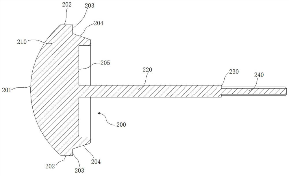
[0052] Such as image 3 As shown, in this embodiment, the end surface of the valve disc 210 away from the valve rod side is the valve disc pressure surface 201. When the fluid flows in the reverse direction, the fluid pressure acts on the valve disc pressure surface 201. When the reverse flow When the fluid velocity exceeds a certain threshold, the control disc 210 compresses the compression spring 300 to the right un...


PUM


Abstract

The invention discloses a speed control one-way valve, and belongs to the technical field of fluid direction control valves. The speed control one-way valve is characterized in that a valve rod guide seat is arranged in a flow control cavity, and a through-flow cavity is arranged in the valve rod guide seat; a speed control valve core component comprises a control valve clack and a valve rod, wherein the control valve clack is located in a valve clack cavity; one side of the valve rod penetrates through a guide hole to be in sliding connection with the valve rod guide seat; a restriction orifice is arranged at the end of one side of the valve rod; a communicated throttling cavity is arranged in the restriction orifice; the restriction orifice is used for closing or opening a notch in one side of the throttling cavity; and a compression spring is arranged between the control valve clack and the valve rod guide seat and used for driving the control valve clack to close or open a notch in one side of the valve clack cavity. The speed control one-way valve aims at the defect that in the prior art, a one-way valve cannot be automatically turned off through a reverse fluid speed control valve, different forward and reverse flow control states of fluid in the speed control one-way valve can be achieved, and the reverse closing action of the valve is determined by the reverse flow speed of the fluid.

Description

technical field [0001] The invention belongs to the technical field of fluid direction control valves, and more specifically relates to a speed control check valve. Background technique [0002] Check valves are widely used in hydraulic control systems to provide a one-way flow path for fluid. The traditional one-way valve is usually provided with a movable valve core and a fixed valve seat, which has a valve seat hole for fluid flow, and the valve disc is always kept in contact with the valve seat hole by the action of a spring, so that the fluid The channel remains normally closed. When the fluid flows in the direction of overcoming the spring force, the disc moves away from the seat hole, and the channel is opened to allow the fluid to flow through the seat hole; and when the fluid moves towards the spring, the same force When flowing in the direction of flow, the fluid acts on the end face of the disc to make it tightly block the seat hole, so that the passage of the fl...

Claims


Application Information

Patent Timeline
Patent Type & Authority Applications(China)
IPC IPC(8): F15B13/02F15B21/00F16K27/02
CPCF15B13/027F15B21/00F16K27/0209
Inventor 王治国王付宇汪和平
Owner ANHUI UNIVERSITY OF TECHNOLOGY
Why Eureka
Try Eureka