Low-friction high-reliability expansion joint for pulverized coal pipeline
A low-friction, pulverized-coal pipeline technology, which is applied to expansion compensation devices, pipe components, and adjustable connections for pipelines, can solve problems affecting the safe operation of units, pipeline cracking, hanging deformation, etc., and achieve friction The effect of small force, avoiding powder leakage in the pipeline, and strong sealing
- Summary
- Abstract
- Description
- Claims
- Application Information
AI Technical Summary
Problems solved by technology
Method used
Image
Examples
specific Embodiment approach 1
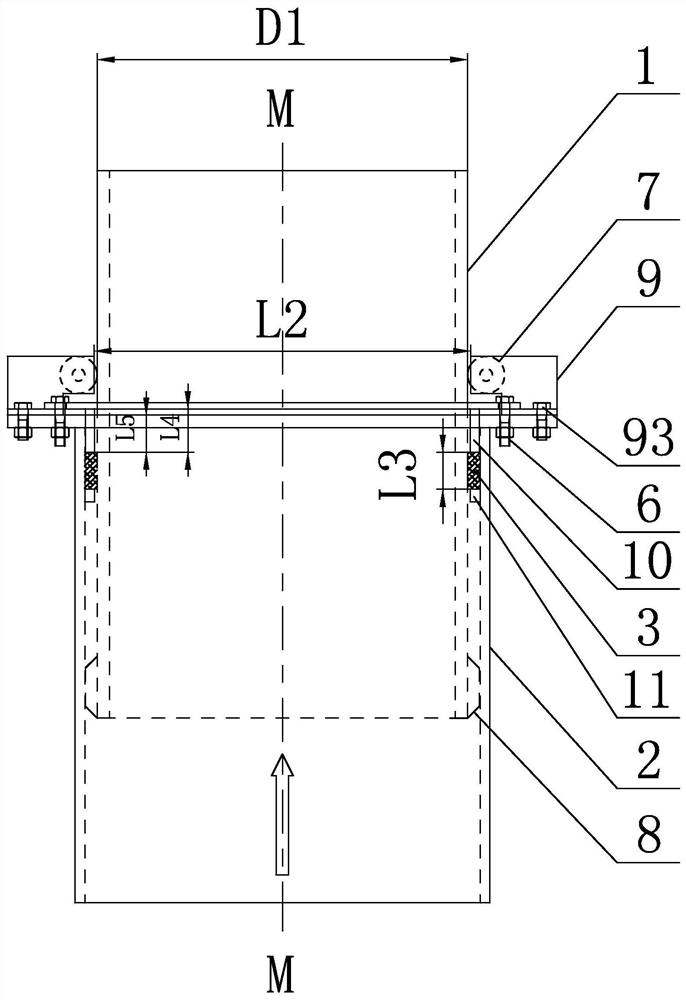
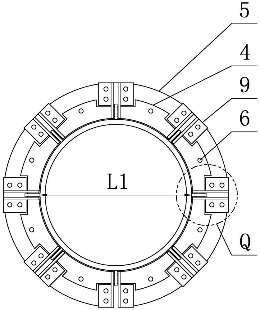
[0021] Specific implementation mode one: combine Figure 1 to Figure 3 Describe this embodiment, a low-friction high-reliability telescopic joint for pulverized coal pipelines in this embodiment, which includes an inner cylinder 1, an outer cylinder 2, a packing 3, an upper ring plate 4, a lower ring plate 5, Compression sleeve 10, stop ring 11, N first connectors 6, N guide wheels 7, N guide rails 8, N support components 9, N≥2, N is a positive integer, and the outer cylinder 2 is vertically arranged , the lower end of the inner cylinder 1 is inserted into the outer cylinder 2 from top to bottom along the axis M-M direction of the outer cylinder 2, the inner cylinder 1 and the outer cylinder 2 can slide and fit, the lower ring plate 5 is set on the outer cylinder 2, and the lower ring plate 5 and the upper end surface of the outer cylinder 2 are located at the same horizontal plane, the inner wall of the lower ring plate 5 is fixedly connected to the outer wall of the outer c...
specific Embodiment approach 2
[0022] Specific implementation mode two: combination figure 1 and figure 2 Describe this embodiment, the first connector 6 of this embodiment includes a first bolt and a first nut, the upper end surface of the upper ring plate 4 is provided with N first through holes in the form of an annular array, and the upper end surface of the lower ring plate 5 is formed in a ring. N second through holes are opened in an array, the first through holes correspond to the second through holes one by one, the upper ring plate 4 is connected with the lower ring plate 5 through the first bolts and the first nuts, and the outer circle of the upper ring plate 4 is N accommodating grooves matching the supporting components 9 are provided in a circular array. In this way, the upper ring plate 4 is detachably connected to the lower ring plate 5 through the first connecting piece 6, which is convenient for disassembly and installation; at the same time, the upper ring plate 4 is spaced apart from ...
specific Embodiment approach 3
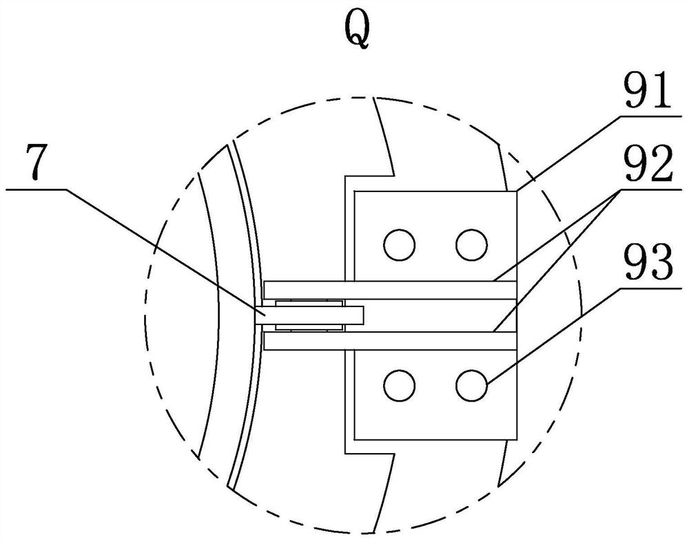
[0023] Specific implementation mode three: combination Figure 1 to Figure 3 Describe this embodiment, each support assembly 9 of this embodiment includes a bottom plate 91, two lug plates 92 and a plurality of second connectors 93, the bottom plate 91 is horizontally arranged on the upper end surface of the lower ring plate 5, the bottom plate 91 is connected through the second The part 93 is detachably connected with the lower ring plate 5, and the two ear plates 92 are relatively arranged on the bottom plate 91 along the vertical direction. It is directly arranged between the two lugs 92, and the shaft ends on both sides of the guide wheel 7 are inserted into the shaft holes of the two lugs 92. In this way, the support assembly 9 supports the guide wheel 7, and the guide wheel 7 can effectively offset the horizontal expansion moment and reduce the sliding friction. Other compositions and connections are the same as those in Embodiment 1 or Embodiment 2.
PUM
 Abstract
Description
Claims
Application Information
 - R&D
- Intellectual Property
- Life Sciences
- Materials
- Tech Scout
- Unparalleled Data Quality
- Higher Quality Content
- 60% Fewer Hallucinations
Browse by: Latest US Patents, China's latest patents, Technical Efficacy Thesaurus, Application Domain, Technology Topic, Popular Technical Reports.
© 2025 PatSnap. All rights reserved.Legal|Privacy policy|Modern Slavery Act Transparency Statement|Sitemap|About US| Contact US: help@patsnap.com


