Sealing flashboard door for biomass feeding

A technology of biomass and sliding doors, which is applied in the direction of valve operation/release devices, sliding valves, valve details, etc., can solve problems such as poor switching, jamming, and blockage, so as to avoid reverse channeling, continuous and reliable switching, and Guaranteed non-deformable effect

Pending Publication Date: 2020-07-31
HARBIN BOILER
View PDF0 Cites 3 Cited by
  • Summary
  • Abstract
  • Description
  • Claims
  • Application Information

AI Technical Summary

Problems solved by technology

[0004] In order to solve the problems of poor sealing effect, poor opening and closing, jamming and blockage of the existing sliding door, the present invention further provides a sealed sliding door for biomass feeding

Method used


Image

  • Sealing flashboard door for biomass feeding
  • Sealing flashboard door for biomass feeding
  • Sealing flashboard door for biomass feeding

Examples


specific Embodiment approach 1

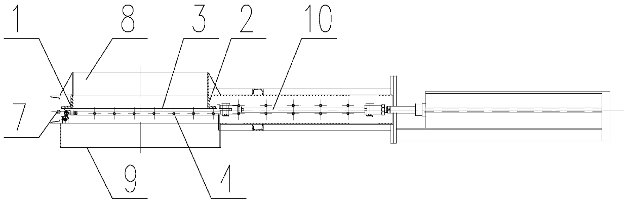
[0024] Specific implementation mode one: combine Figure 1 to Figure 6 Describe this embodiment, this embodiment is a kind of sealing gate for biomass feeding, which includes the front end 1 of the valve body, the rear end 2 of the valve body, the feed port 8, the discharge port 9, the front end 1 of the valve body and The rear end 2 of the valve body is located at the front and rear ends of the valve body, and the feed inlet is fixedly installed between the front end 1 of the valve body and the rear end 2 of the valve body. The sealed gate for biomass feeding also includes The flashboard assembly and the locking assembly, the flashboard assembly is slidingly connected to the bottom of the valve body front end 1 and the valve body rear end 2 respectively, the discharge port 9 is located at the bottom of the flashboard assembly, and the locking mechanism is connected to the flashboard assembly.

[0025] After the valve body is manufactured, the sealing surface of the valve body...

specific Embodiment approach 2

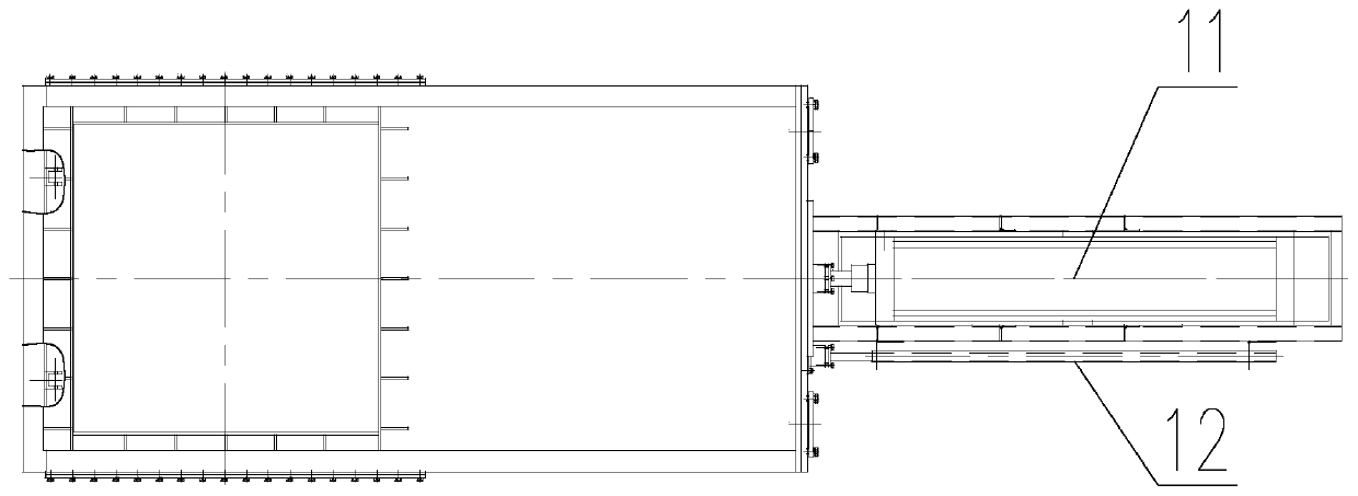
[0026] Specific implementation mode two: combination figure 1 Describe this embodiment, the flashboard assembly described in this embodiment includes a flashboard 3, a connecting rod 10, and a cylinder 11. Slidingly connected, one end of the connecting rod 10 is hinged with the flashboard 3, and the other end of the connecting rod 10 is connected with the cylinder 11. The limiting device 12 is in sliding connection with the cylinder 11 .

[0027] Other components and connections are the same as those in the first embodiment.

specific Embodiment approach 3

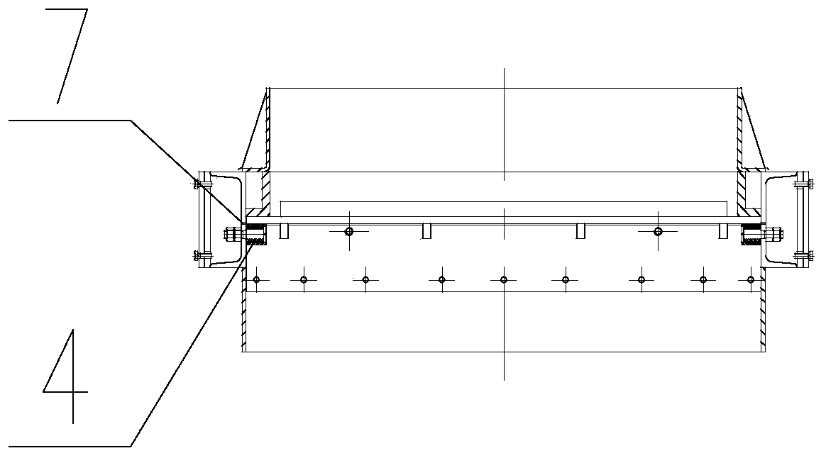
[0028] Specific implementation mode three: combination Figure 4 To describe this embodiment, the front end of the board 3 described in this embodiment is a wedge-shaped structure 3-1.

[0029] Such setting can effectively remove materials and impurities stuck on the sealing surface of the valve body, ensure reliable sealing of the sliding door in the closed state, and prevent material jamming.

[0030] Other components are the same as those in the second embodiment in terms of connections.


PUM


Abstract

The invention relates to a sealing flashboard door, in particular to a sealing flashboard door for biomass feeding, and solves the problems of poor sealing effect, unsmooth opening and closing, jamming and blockage of an existing flashboard door. The sealing flashboard door for biomass feeding comprises a valve body front end, a valve body rear end, a feed port and a discharge port, wherein the valve body front end and the valve body rear end are both positioned at the front end and the rear end inside a valve body, the feed port is fixedly installed between the front end of the valve body andthe rear end of the valve body and located on the upper portion of the valve body, and the discharge port is located on the lower portion of the valve body. The sealing flashboard door for biomass feeding also comprises a plugboard assembly and a locking assembly, the plugboard assembly is in sliding connection with the bottom of the front end of the valve body and the bottom of the rear end of the valve body, and the locking mechanism is connected with the plugboard assembly. The sealing flashboard door can effectively solve the problems of unsmooth opening and closing, jamming, blocking, high failure rate and the like after frequent opening and closing.

Description

technical field [0001] The invention relates to a sealed sliding door, in particular to a sealed sliding door used for biomass feeding. Background technique [0002] Biomass power generation technology is an advanced power generation technology that is energy-saving and environmentally friendly. It is currently divided into three technologies: biomass direct combustion, co-combustion and biomass gasification. The above technologies are all very important for the continuity and sealing of biomass feedstock high demands. If the feeding system is not tightly sealed, it will lead to high-temperature flue gas backflow, affecting the operation of biomass incinerators or biomass gasifiers, especially for positive pressure gasifiers, whose flue gas contains a large amount of combustible gases (such as carbon monoxide, methane, hydrogen, etc.), if it is reversed into the feeding system, it may cause biomass combustion or explosion accidents. [0003] The biomass size changes greatl...

Claims


Application Information

Patent Timeline
Patent Type & Authority Applications(China)
IPC IPC(8): F16K3/02F16K3/30F16K31/122
CPCF16K3/0281F16K3/30F16K31/122
Inventor 刘恒宇孙浩李伟石立新尹贻龙宋建勋周玉飞
Owner HARBIN BOILER
Why Eureka
Try Eureka