
Gas pressure intensity testing system for pneumatic tension compensator

A gas pressure and testing system technology, applied in the direction of measuring fluid pressure, instruments, measuring devices, etc., can solve the problems of affecting driving safety and operating efficiency, requiring high installation accuracy, increasing costs, etc.

Active Publication Date: 2021-04-13
中铁七局集团电务工程有限公司
View PDF7 Cites 0 Cited by
  • Summary
  • Abstract
  • Description
  • Claims
  • Application Information

AI Technical Summary

Problems solved by technology

[0004] 1. There are deficiencies in the pulley compensation device: (1) Poor wind stability, which affects driving safety and operating efficiency
(2) The pendant has the risk of falling or losing blocks, which affects the compensation accuracy and maintenance workload
(3) Not suitable for application in long tunnels and large bridges, increasing costs and prolonging construction period
(5) Unsightly
Insufficient: (1) High cost
(2) Low yield (sand casting is used in China)
(3) Poor wind resistance
(4) Unsightly
There are deficiencies: (1) High requirements for installation accuracy
(2) The compensation stroke is limited
(3) The spring is prone to plastic deformation, and the compensation effect deteriorates
At the same time, the gas pressure in the cylinder of the pneumatic tension compensator is one of the important parameters affecting the work of the pneumatic tension compensator. Misjudgment

Method used


Image

  • Gas pressure intensity testing system for pneumatic tension compensator
  • Gas pressure intensity testing system for pneumatic tension compensator
  • Gas pressure intensity testing system for pneumatic tension compensator

Examples


Embodiment Construction

[0033] The gas pressure testing system for a pneumatic tension compensator provided by the present invention will be described in detail below with reference to the drawings and embodiments.

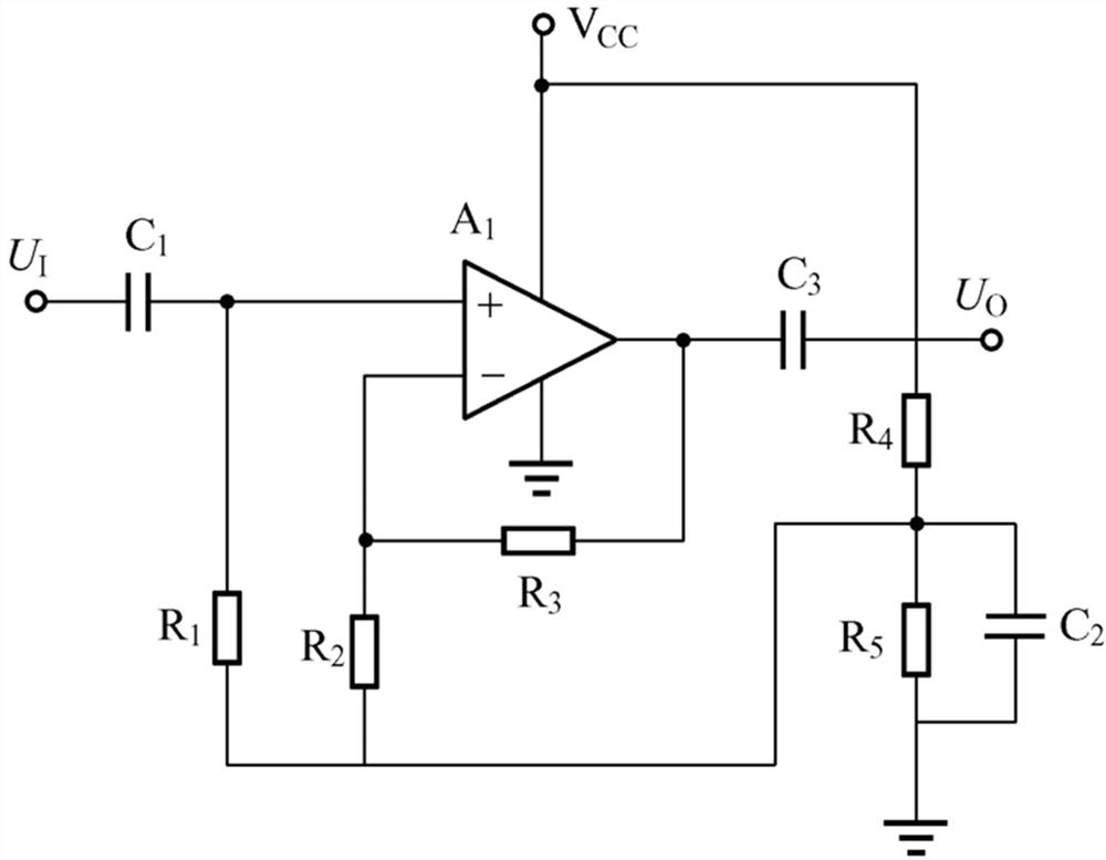
[0034] Such as figure 1 As shown, the gas pressure testing system for a pneumatic tension compensator provided by the present invention includes a gas pressure sensor, a signal processing circuit, an image sensor, an image acquisition and setting unit, a storage unit, a data transmission communication unit, a comparison unit and an alarm unit.

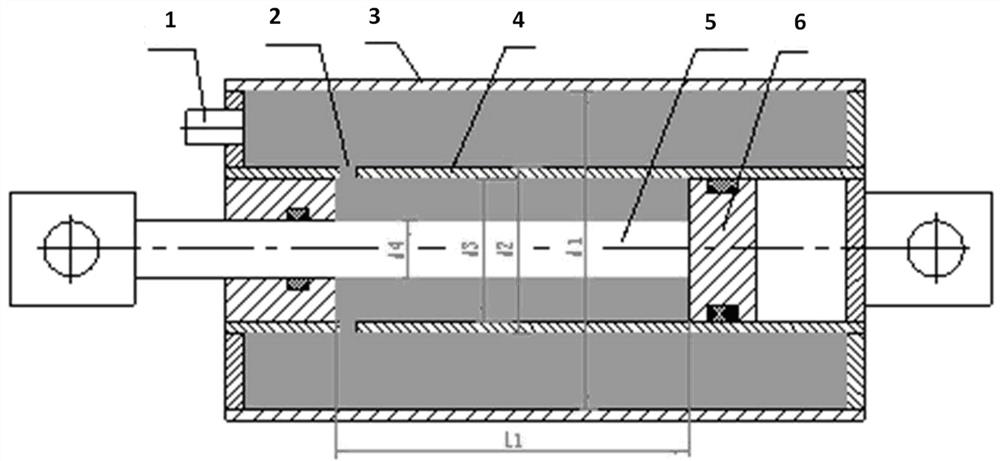
[0035] Such as figure 2 As shown, the pneumatic tension compensator includes an inflation valve 1, a vent hole 2, an air reservoir 3, a cylinder 4, a piston rod 5 and a piston 6, the inflation valve 1 is connected to the gas reservoir 3, and the gas reservoir 3 is connected to the cylinder The cylinder 4 is connected, the piston 6 is arranged at one end of the piston rod 5, and the upper and lower parts of the piston 6 are respectively connecte...


PUM


Abstract

The invention provides a gas pressure intensity testing system for a pneumatic tension compensator, the pneumatic tension compensator comprises an inflation valve, a vent hole, an air storage cylinder, a cylinder barrel, a piston rod and a piston, the inflation valve is connected with the air storage cylinder, the air storage cylinder is connected with the cylinder barrel through the vent hole, and the piston is arranged at one end of the piston rod. The upper portion and the lower portion of the piston are connected with the upper portion and the lower portion of the inner wall of the cylinder barrel respectively, and then a gas pressure sensor, a signal processing circuit, an image sensor, an image acquisition setting unit, a storage unit, a data transmission communication unit, a comparison unit and an alarm unit are used for testing gas pressure intensity data in the cylinder barrel when the piston is located at different positions. The image acquisition setting unit is used for reducing the influence of scintillation light during acquisition of the image sensor, and the signal processing circuit is used for improving the gas pressure intensity test precision.

Description

technical field [0001] The invention relates to the field of intelligent monitoring, in particular to a gas pressure testing system for a pneumatic tension compensator. Background technique [0002] In order to ensure the good current flow of the locomotive pantograph (electric railway train power supply system - pantograph, also known as the power transmission frame), it is required that the contact wire and catenary cable must maintain a certain tension, and the contact wire and catenary cable must be The tension change of the cable is compensated at any time, and the length of the contact line and the catenary cable is changed by the change of the ambient temperature. [0003] Traditional tension compensation devices mainly include: pulley compensation device, ratchet compensation device, spring compensation device. Although it can be used, there are certain deficiencies. [0004] 1. There are deficiencies in the pulley compensation device: (1) The wind stability is poo...

Claims


Application Information

Patent Timeline
IPC IPC(8): G01L11/00
CPCG01L11/00
Inventor 刘培峰于小四郭峰韦宝泉郭彦路尚德政
Owner 中铁七局集团电务工程有限公司
Learn More