Charge pump with wide locking range and low current mismatch
A locking range, charge pump technology, applied in the field of microelectronics, can solve the problems of restricting charge pump application, charge sharing, current mismatch, etc.
- Summary
- Abstract
- Description
- Claims
- Application Information
AI Technical Summary
Problems solved by technology
Method used
Image
Examples
Embodiment
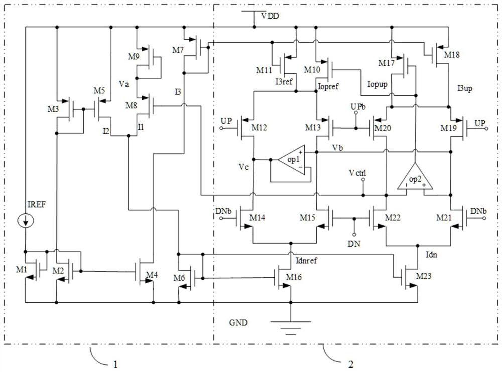
[0021] A wide lock range low current mismatch charge pump such as figure 2 As shown, including charge pump bias circuit 1, charge pump core circuit 2;
[0022] Wherein, the signal output terminal of the charge pump bias circuit 1 is connected to the signal input terminal of the charge pump core circuit 2, and the signal output terminal of the charge pump core circuit 2 is connected to the signal input of the charge pump bias circuit 1 terminal; the charge pump bias circuit 1 provides a bias signal for the charge pump core circuit 2, and the charge pump core circuit 2 provides charge / discharge current for the filter capacitor of the subsequent stage circuit.
[0023] As a preferred technical solution, such as figure 2 As shown, the charge pump bias circuit 1 includes: reference current source IREF, NMOS transistor M1, NMOS transistor M2, PMOS transistor M3, NMOS transistor M4, PMOS transistor M5, NMOS transistor M6, PMOS transistor M7, PMOS transistor M8 and PMOS transistor...
PUM
 Abstract
Description
Claims
Application Information
 - R&D
- Intellectual Property
- Life Sciences
- Materials
- Tech Scout
- Unparalleled Data Quality
- Higher Quality Content
- 60% Fewer Hallucinations
Browse by: Latest US Patents, China's latest patents, Technical Efficacy Thesaurus, Application Domain, Technology Topic, Popular Technical Reports.
© 2025 PatSnap. All rights reserved.Legal|Privacy policy|Modern Slavery Act Transparency Statement|Sitemap|About US| Contact US: help@patsnap.com


