Supercharge Your Innovation With Domain-Expert AI Agents!

Flow pulse counter and application thereof

A pulse counter and flow technology, which is used in measuring/indicating equipment, metal processing mechanical parts, metal processing equipment, etc. Effect

Pending Publication Date: 2021-04-16
东莞市埃弗米数控设备科技有限公司
View PDF5 Cites 0 Cited by
  • Summary
  • Abstract
  • Description
  • Claims
  • Application Information

AI Technical Summary

Problems solved by technology

[0002] In the multi-faceted milling head of CNC machine tools, the spindle piston must have tool release and in-position detection when changing tools, otherwise it will easily lead to risks such as tool drop and damage to related parts of the tool magazine.
However, due to the rotation of the two rotary axes in the universal milling head, the wires of the proximity switch cannot be connected to the electrical cabinet through the entire milling head body. Therefore, most milling heads judge the cutting tool indirectly through the pressure relay of the hydraulic system. Whether the cylinder is in place, that is, after the knife is in place, the oil pressure of the knife cylinder rises, causing the signal of the pressure relay to trigger, and this signal is used to judge that the piston is in place
This method has great hidden dangers. For example, once the oil cylinder and piston are stuck and the knife is not in place, the signal of the pressure relay will also be triggered, resulting in misjudgment by the CNC system.
The existing pulse counter is not suitable for detecting whether the milling head is installed in place, and the existing pulse counter has a complex structure, inconvenient installation, and low precision

Method used


Image

  • Flow pulse counter and application thereof
  • Flow pulse counter and application thereof
  • Flow pulse counter and application thereof

Examples


Embodiment 2

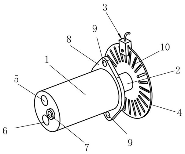
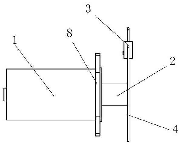
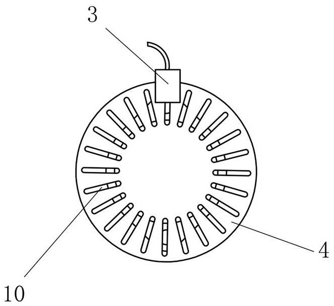
[0031] Such as figure 1 As shown, an application of a flow pulse counter, the oil inlet pipe 5 of the flow pulse counter is externally connected to the reversing valve of the multi-face milling head of the CNC machine tool, and the oil return pipe 6 of the flow pulse counter is externally connected to the cutting tool of the multi-face milling head of the CNC machine tool cylinder, when a certain flow of oil enters the knife piston through the hydraulic motor, the hydraulic motor 1 drives the code disc 5 to rotate, and the photoelectric switch 3 detects the number of revolutions of the code disc 5 to determine the volume of the oil flowing into the hydraulic motor 1. In order to judge whether the multi-faceted milling head of the CNC machine tool is in place, this test method can use the flow pulse counter to judge whether the multi-faceted milling head of the CNC machine tool is in place, so that no pressure relay signal is needed. This detection method is accurate and reliabl...


PUM


Abstract

The invention relates to the technical field of counters, in particular to a flow pulse counter. The flow pulse counter comprises a hydraulic motor, a rotating shaft, a photoelectric switch and a coded disc. Oil entering through an oil inlet pipeline drives the hydraulic motor to rotate, and the hydraulic motor drives the rotating shaft and the coded disc to rotate. The photoelectric switch counts the number of the seams through which the coded disc rotates, and then the volume of the oil entering the hydraulic motor is obtained through conversion, so that whether an oil cylinder is in place or not can be judged, and a numerical control system can more conveniently and accurately judge the position of a cutter beating piston. The problem that a proximity switch wire cannot penetrate through a milling head body and the problem of reliability of a pressure relay are solved. According to the detection method, whether the cutter beating of the multi-surface milling head of a numerical control machine tool is in place or not can be judged through the flow pulse counter, so that pressure relay signals are not needed, the detection method is accurate and reliable, and false triggering of the numerical control system is avoided.

Description

technical field [0001] The invention relates to the technical field of pulse counters, in particular to a flow pulse counter and its application. Background technique [0002] In the multi-faceted milling head of CNC machine tools, the spindle piston must have tool release and in-position detection when changing tools, otherwise it will easily lead to risks such as tool drop and damage to related parts of the tool magazine. However, due to the rotation of the two rotary axes in the universal milling head, the wires of the proximity switch cannot be connected to the electrical cabinet through the entire milling head body. Therefore, most milling heads judge the cutting tool indirectly through the pressure relay of the hydraulic system. Whether the cylinder is in place, that is, after the knife is in place, the oil pressure of the knife cylinder rises, causing the signal of the pressure relay to trigger, and this signal is used to judge that the piston is in place. This metho...

Claims


Application Information

Patent Timeline
IPC IPC(8): B23Q17/22
Inventor 余学林黄永生
Owner 东莞市埃弗米数控设备科技有限公司
Features
  • R&D
  • Intellectual Property
  • Life Sciences
  • Materials
  • Tech Scout
  • Unparalleled Data Quality
  • Higher Quality Content
  • 60% Fewer Hallucinations
Learn More