
Gas flow detection system

A detection system and gas flow technology, applied in the field of compressors, can solve problems such as large measurement error, high cost, and small fluctuations in detection pressure, and achieve the effects of simplifying structure, saving costs, and reducing noise

Pending Publication Date: 2021-04-16
HAOMI POWER EQUIP CO LTD
View PDF0 Cites 0 Cited by
  • Summary
  • Abstract
  • Description
  • Claims
  • Application Information

AI Technical Summary

Problems solved by technology

Every compressor manufacturer will have a matching inspection system, but such systems will have the following defects: (1) Each inspection system is only for a certain type of compressor. When producing different types of compressors, multiple sets are required The cost of the detection system is relatively high; (2) During the measurement process, it is necessary to ensure that the pressure remains stable, but actually affected by factors such as the external environment, the detection pressure will fluctuate slightly, resulting in large measurement errors

Method used


Image

  • Gas flow detection system

Examples


Embodiment 1

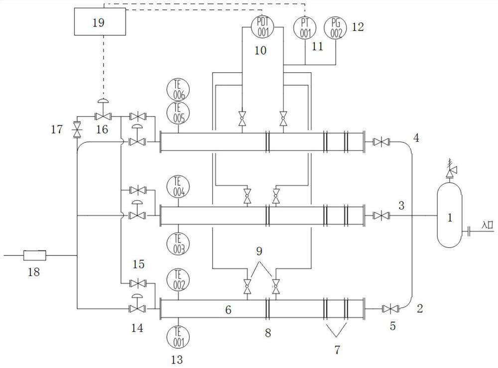
[0028] A flow detection system, its structure is as follows figure 1 As shown, the gas pipeline inlet of the detection system is connected to the compressor to be tested (the compressor to be tested is not shown in the figure), and then the gas storage tank 1 is installed, and the gas storage tank 1 is connected to the first detection unit 2 through three pipelines respectively. , the second detection unit 3 and the third detection unit 4, the same types of parts are arranged on the three monitoring units, but the specifications of the parts used are different, taking the first detection unit 2 as an example:

[0029] The entrance of the first detection unit 2 is provided with a gate valve 5, which is then connected to the flow cylinder 6. Two rectification orifice plates 7 are arranged at the front end of the flow cylinder 6. The orifice plate 8 is detected, and then flows out of the flow cylinder 6, and a temperature sensor 13 is arranged at the rear end of the flow cylinder...


PUM


Abstract

The invention relates to a gas flow detection system which is connected with a gas outlet of a compressor to be detected and comprises a gas storage tank and a plurality of detection units arranged in parallel, and each detection unit comprises a gate valve, a flow cylinder and a pressure adjusting unit which are connected in sequence. A plurality of rectification orifice plates are arranged at the inlet end of the flow cylinder; a detection orifice plate is arranged in the middle of the flow cylinder; a differential pressure sensor, a pressure gauge and a pressure sensor are arranged in front of and behind the detection orifice plate, and a temperature sensor is arranged at the rear end of the flow cylinder. A plurality of flow cylinders are combined for use according to actual requirements, and each flow cylinder can work independently and share one differential pressure detection assembly and one pressure stabilizing assembly; the compressed gas passing through the flow cylinder is finally exhausted through the silencer; each detection instrument has a remote transmission function and can transmit data to a PLC or a computer system.

Description

technical field [0001] The invention relates to the technical field of compressors, in particular to a gas flow detection system. Background technique [0002] Compressor is a device used to compress low-pressure gas into high-pressure gas, which plays an important role in chemical, pharmaceutical, metallurgical and other industries. There are many indicators to evaluate the performance of compressors, one of which is the flow rate, which can reflect the processing capacity of the compressor, and is a must-do test for each compressor before leaving the factory. Every compressor manufacturer will have a matching inspection system, but such systems will have the following defects: (1) Each inspection system is only for a certain type of compressor. When producing different types of compressors, multiple sets are required The cost of the detection system is relatively high; (2) During the measurement process, it is necessary to ensure that the pressure is kept stable, but actu...

Claims


Application Information

Patent Timeline
IPC IPC(8): G01F1/42G01F1/50G01F15/10G01F15/06
Inventor 杨小平殷军
Owner HAOMI POWER EQUIP CO LTD
Learn More