Display panel and display device

A technology for display panels and substrates, applied in nonlinear optics, instruments, optics, etc., can solve problems such as insufficient curing of the frame glue, adhesion and detachment of the frame glue and the substrate, etc., to improve the curing effect, increase the scattering and reflection paths, and ensure The effect of stable bonding

Active Publication Date: 2021-04-16
TCL CHINA STAR OPTOELECTRONICS TECH CO LTD
View PDF5 Cites 0 Cited by
  • Summary
  • Abstract
  • Description
  • Claims
  • Application Information

AI Technical Summary

Problems solved by technology

However, when the frame glue curing process in the existing manufacturing process is faced with narrow bezel and ultra-narrow bezel LCD products, the problem of insufficient curing of the frame glue and the adhesion and detachment of the frame glue from the substrate often occurs.

Method used


Image

  • Display panel and display device
  • Display panel and display device
  • Display panel and display device

Examples


Embodiment 1

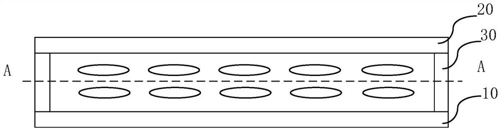
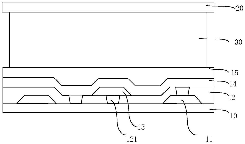
[0047] Please refer to image 3 , Embodiment 1 of the present application provides a display panel, the display panel includes: a first substrate 10, a second substrate 20, and a sealant 30 disposed between the first substrate 10 and the second substrate 20, the first substrate 10 and the second substrate 20 are fixedly connected by a sealant 30 . The display panel also includes a light-scattering layer 12 disposed between the first substrate 10 and the sealant 30 . When curing the sealant 30 in the display panel, an ultraviolet (UV) light emitting device may be disposed on the side of the first substrate 10 away from the sealant 30 . The ultraviolet light emitting device is used to generate UV light required for curing the sealant 30 . The UV light emitted by the ultraviolet light emitting device passes through the scattering layer 12 and then reaches the area of ​​the sealant 30 . Due to the setting of the astigmatism layer 30, the scattering and reflection paths of the U...

Embodiment 2

[0060] Please refer to Figure 5 with Figure 4 , Embodiment 2 of the present application provides a display panel, the display panel includes a first substrate 10, a second substrate 20, and a sealant 30 disposed between the first substrate 10 and the second substrate 20, the first substrate 10 It is fixedly connected with the second substrate 20 through the sealant 30 . The display panel further includes a light-scattering layer 12 disposed between the first substrate 10 and the sealant 30 or between the second substrate 20 and the sealant 30 .

[0061] The structure of the display panel provided by the second embodiment of the present application is similar to that of the display panel provided by the first embodiment of the present application, and the similarities will not be repeated in this embodiment. The difference is that the light scattering structure 121 in the second embodiment of the present application is completely covered by the first metal wiring 111 and th...

Embodiment 3

[0063] Please refer to Image 6 with Figure 4 , Embodiment 3 of the present application provides a display panel, the display panel includes: a first substrate 10, a second substrate 20, and a sealant 30 disposed between the first substrate 10 and the second substrate 20, the first substrate 10 and the second substrate 20 are fixedly connected by a sealant 30 . The display panel also includes a light-scattering layer 12 disposed between the first substrate 10 and the sealant 30 .

[0064] The structure of the display panel provided by the third embodiment of the present application is similar to that of the display panel provided by the first embodiment of the present application, and the same parts will not be repeated in this embodiment. The difference is that the light-scattering structure 121 in the third embodiment of the present application is a groove. It should be noted that the groove only represents that the light-scattering structure 121 is not set through the li...


PUM


Abstract

The embodiment of the invention discloses a display panel and a display device. The display panel comprises a first substrate, a second substrate and frame glue arranged between the first substrate and the second substrate, the frame glue is arranged between the first substrate and the second substrate, and the first substrate and the second substrate are fixedly connected through the frame glue. The display panel further comprises a light scattering layer arranged between the first substrate and the frame glue or between the second substrate and the frame glue. According to the display panel and the display device, the light scattering layer is arranged in the area corresponding to the frame glue, so that scattering and reflecting paths of ultraviolet curing light are increased in the frame glue curing process of the display panel and the display device, the curing effect of the frame glue in the display panel and the display device is improved, and stable bonding between the frame glue and the substrate is guaranteed.

Description

technical field [0001] The present application relates to the field of display technology, in particular to a display panel and a display device. Background technique [0002] As end users pursue the ultimate appearance of the display and the highly immersive experience of the display in actual commercial / home application scenarios, the demand for LCD (Liquid Crystal Display) displays with extremely narrow borders has become increasingly prominent. [0003] The bezel area of ​​LCD has changed from 6mm or more in the early years to the common 3mm or less than 2mm now, and even individual panel manufacturers have begun to challenge the ultra-narrow bezel below 1mm in terms of process technology. As the frame area of ​​the LCD display continues to narrow, it directly leads to the narrowing of the frame glue area used to adhere and fix the upper and lower substrates, and the narrowing of the frame glue area will directly affect the adhesion effect of the upper and lower substrat...

Claims


Application Information

Patent Timeline
Patent Type & Authority Applications(China)
IPC IPC(8): G02F1/1335G02F1/1339
Inventor 曹武
Owner TCL CHINA STAR OPTOELECTRONICS TECH CO LTD
Why Eureka
Try Eureka