
Large-scale MIMO capacity improving method based on unmanned aerial vehicle cluster deployment

A technology for cluster deployment and capacity improvement, applied in baseband system components, wireless communication, network planning, etc., can solve wireless communication uncertainty, reduce communication quality, fail to meet UAV communication control performance requirements, and consume large communication energy To achieve the effect of improving battery life and real-time control capability, shortening communication control delay, and reducing communication energy consumption

Active Publication Date: 2021-04-16
SOUTHEAST UNIV
View PDF4 Cites 7 Cited by
  • Summary
  • Abstract
  • Description
  • Claims
  • Application Information

AI Technical Summary

Problems solved by technology

[0004] The UAV cluster deployment method based on center optimization control requires UAV to communicate with the optimization control center in real time, which will consume a lot of communication energy consumption. On the other hand, wireless communication uncertainty caused by physical phenomena such as wireless channel fading will Seriously reduce the quality of communication, which does not meet the performance requirements of UAV communication control for high-reliability and low-latency communication
In addition, it is difficult for UAVs to obtain the global information of the network in actual situations, so there are some defects in the centralized deployment method of UAV clusters using global information

Method used


Image

  • Large-scale MIMO capacity improving method based on unmanned aerial vehicle cluster deployment
  • Large-scale MIMO capacity improving method based on unmanned aerial vehicle cluster deployment
  • Large-scale MIMO capacity improving method based on unmanned aerial vehicle cluster deployment

Examples


Embodiment Construction

[0042] The present invention will be further described below in conjunction with drawings and embodiments.

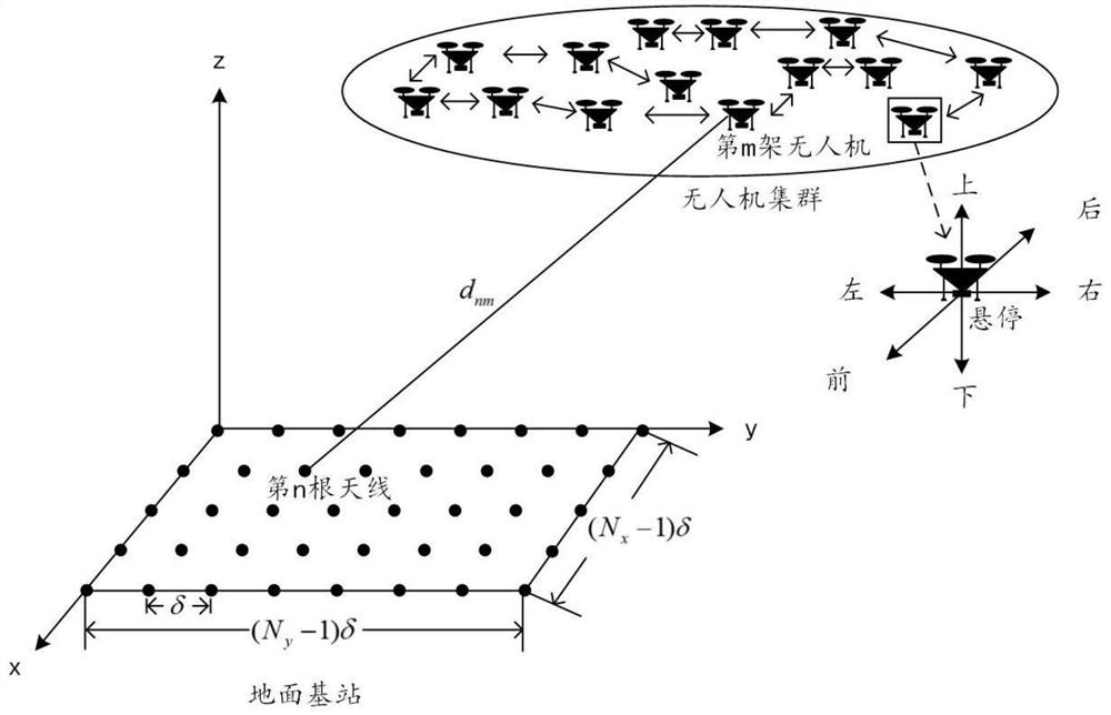
[0043] In the embodiment of the present invention, such as figure 1 The network architecture of the massive MIMO capacity improvement method based on UAV cluster deployment is shown. The UAV cluster is located in the area above the ground base station. M cluster UAVs are equipped with single antennas, and each UAV is a rotor UAV. , the ground base station is configured with N antennas. In order to simplify the analysis, the number M of cluster UAVs is equal to the number N of ground base station antennas, that is, M=N, then the received signal of the ground base station can be expressed as:

[0044]

[0045] Among them, E s is the transmission power, s is the transmission signal of the UAV cluster, n 0 is zero mean, unit variance N 0 The complex white Gaussian noise of H is the MIMO channel matrix of the uplink communication link. Neglecting the distance differe...


PUM


Abstract

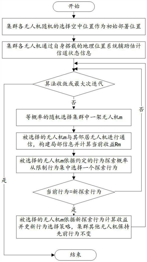
The invention discloses a large-scale MIMO capacity improving method based on unmanned aerial vehicle cluster deployment, and the method comprises the steps: firstly enabling each single-antenna unmanned aerial vehicle to be randomly deployed in an area above a multi-antenna ground base station, and enabling each unmanned aerial vehicle to assist in estimating channel state information through a geographic position system; randomly selecting one unmanned aerial vehicle to communicate with the neighbor unmanned aerial vehicle, constructing local information, and calculating the current income; learning deployment behaviors according to earnings, and keeping the positions of other unmanned aerial vehicles unchanged; and finally, determining the optimal deployment position of each unmanned aerial vehicle after a plurality of rounds of interaction. According to the invention, the channel capacity is improved by adjusting the deployment position of each unmanned aerial vehicle; and deployment is completed only by using local information without an optimization control center, so that the communication energy consumption is reduced, the communication control time delay is shortened, and the endurance and real-time control capability of the unmanned aerial vehicle cluster are improved. Applicable wireless communication scenarios include, but are not limited to, high density venue communications, battlefield communications, disaster relief and rescue communications.

Description

technical field [0001] The invention belongs to the field of unmanned aerial vehicle cluster communication, and in particular relates to a large-scale MIMO (multiple input multiple output, MIMO) capacity improvement method based on unmanned aerial vehicle cluster deployment to improve the channel capacity of an uplink communication link. Background technique [0002] In the development process of mobile communication, MIMO technology is the key technology to improve the data rate and resist interference in mobile communication. In recent years, with the continuous increase of frequency bands and the rapid increase of the number of users, the number of antennas at the transceiver end has increased sharply. Based on massive MIMO Mobile communication technology has become a hot topic in academia and industry. UAV communication has the characteristics of high-speed mobility, deployment flexibility, and strong line-of-sight communication. It can fully develop massive MIMO technol...

Claims


Application Information

Patent Timeline
IPC IPC(8): H04W16/18H04W16/22H04B7/0413H04B7/185H04L25/02
CPCY02D30/70
Inventor 高宁金石李潇
Owner SOUTHEAST UNIV
Learn More