Mouse caudal vein blood sampling system
A tail vein and mouse technology, applied in the field of medical experiments, can solve the problems of air bubbles, difficulty in ensuring tail stability, interference, etc., and achieve the effect of overcoming air bubbles, avoiding interruption of blood collection, and reducing the amount of air bubbles mixed in
- Summary
- Abstract
- Description
- Claims
- Application Information
AI Technical Summary
Problems solved by technology
Method used
Image
Examples
Embodiment 1
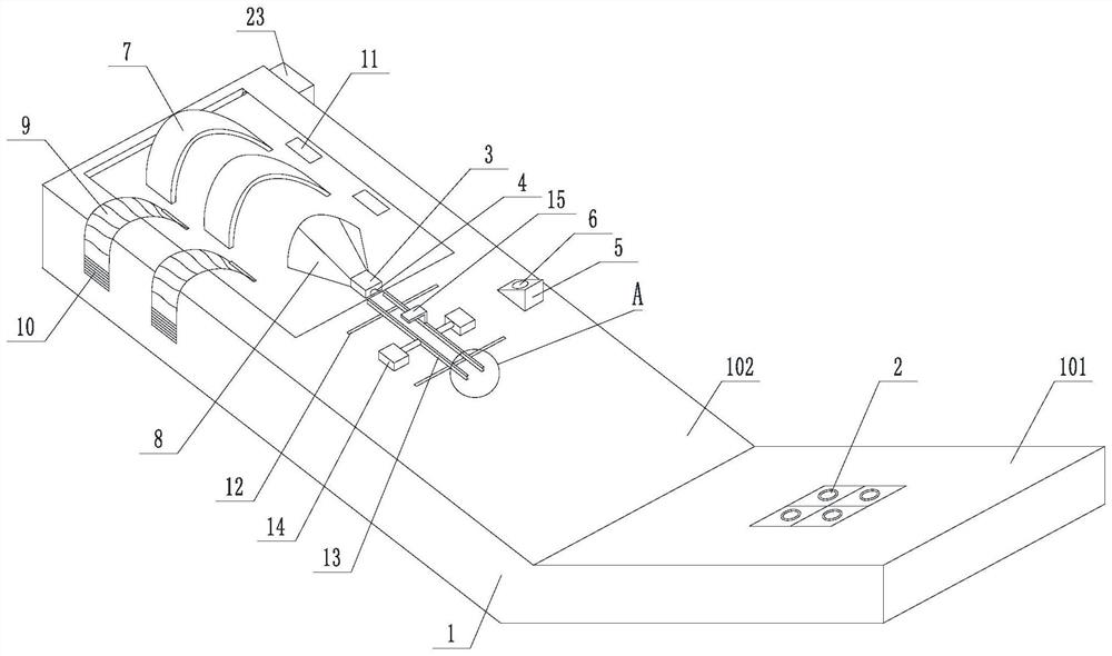
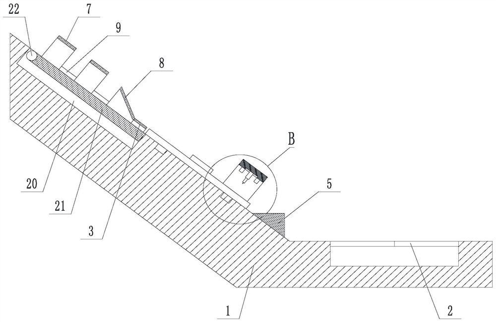
[0042]Such asfigure 1 versusfigure 2 A mouse tail vein tension system, including a small body 1, a table body 1 including a horizontal plane 101, an inclined surface 102, a horizontal plane 101, a casing, and a slope 102, and then set a mouse fixing assembly in turn. Mouse tail positioning device 3, sage clamping assembly, the mouse tail positioning device 3 includes a passage 4 for a murray; further comprising a bearing 5 located on the bevel 102, the upper surface of the upper surface 5 is parallel to the horizontal plane 101, and A jack 6 for placing an EP tube is opened on the upper surface of the jack 5.
[0043]Among them, the mouse fixing assembly includes a plurality of curved limit members 7, and the height and width of the internal passage of the half tapeed tube 8 are located between the arc limit member 7 and the mouse tail positioning device 3. The inclined direction is gradually reduced from the top and bottom, and the bottom end of the heating cylinder 8 is in communicat...
Embodiment 2
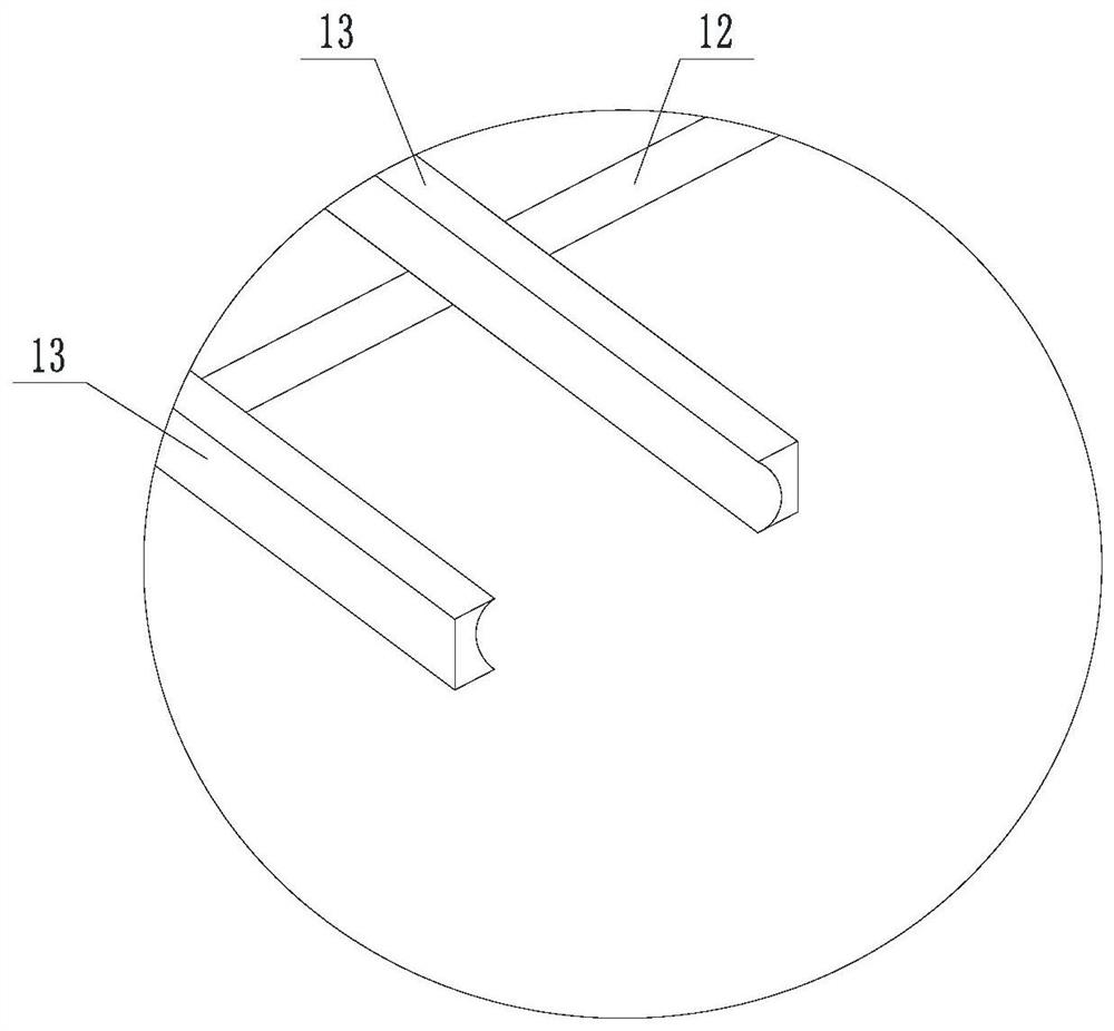
[0046]Such asFigure 1 to 4A mouse adjuverelet blood system, on the basis of Example 1, the mouse tail clamp assembly includes a first sliding rail 12 disposed on the inclined surface 102, sliding two in the first sliding rail 12. The root clamping rod 13, the axis of the first slide rail 12 is parallel to the horizontal plane 101; any one of the clamping rods 13 connects the first driving member 14, the first driving member 14, the first drive The member 14 is used to drive the connected clamping rod 13 to perform a linear movement along the first sliding rail 12. Any side surface of any one of the clamping rods 13 is in the direction of the direction in which the clamping rod 13 is in a concave curved surface. One of the tops of one of the clamping rods 13 is connected to the mounting member 15, and the mounting member 15 extends toward the other holding rod 13; the mouse tail sensing device 16, the telescopic device 17, and the telescopic device 17 are fixed at the bottom of the m...
Embodiment 3
[0060]On the basis of the second embodiment, the groove 20 is opened on the sliding surface 102, and the carrier plate 21 is provided in the groove 20, and the top of the carrier plate 21 is rotatable with the groove 20 side wall, and further includes driving the shaft 22 rotation. The third drive 23; the mouse fixing assembly is located on the carrier plate 21. The carrier plate 21 is a magnetic metal plate. Mouse tail positioning device 3Figure 5 As shown, a number of magnets 24 are embedded at the bottom; the passage 4 is open from the bottom surface of the mouse tail positioning device 3, and the inner wall of the passage 4 coated a layer of elastic material 25.
[0061]Preferably, the magnetic metal plate is a iron plate, the elastic material is a rubber pad.
[0062]The blood circulation of this embodiment is:
[0063]Step S2 is specifically: first remove the mouse tail positioning device, and then fix the mice after the mouse fixing assembly, then the noise positioning device is buckl...
PUM
 Abstract
Description
Claims
Application Information
 - R&D
- Intellectual Property
- Life Sciences
- Materials
- Tech Scout
- Unparalleled Data Quality
- Higher Quality Content
- 60% Fewer Hallucinations
Browse by: Latest US Patents, China's latest patents, Technical Efficacy Thesaurus, Application Domain, Technology Topic, Popular Technical Reports.
© 2025 PatSnap. All rights reserved.Legal|Privacy policy|Modern Slavery Act Transparency Statement|Sitemap|About US| Contact US: help@patsnap.com


