Automatic punching machine for drill rod joint machining

A technology for automatic punching and drill pipe joints, applied in metal processing equipment, piercing tools, forming tools, etc., can solve the problems of time-consuming, labor-intensive, low efficiency, and relying on labor

Pending Publication Date: 2021-04-20
江苏拓海煤矿钻探机械有限公司
View PDF0 Cites 0 Cited by
  • Summary
  • Abstract
  • Description
  • Claims
  • Application Information

AI Technical Summary

Problems solved by technology

The main steps of the existing drill pipe joint processing are: blanking - heating - forging - die forging - punching - post-forging treatment - rough machining - heat treatment, wherein punching is the main process of drill pipe joint processing, punching is in The die bar is used on the punching machine to eject the inner skin of the drill pipe joint after forging, but the existing punching machines have the following problems: First, the blanking of the punching machine generally relies on manual work, and the drill pipe after punching The temperature of the joint is high, which is very easy to burn the workers. At the same time, the efficiency of the whole blanking process is low, time-consuming and laborious; second, the mold rod needs to be in direct contact with the drill pipe joint with a higher temperature. The increase will affect the mechanical properties and deformation resistance of the mold rod

Method used


Image

  • Automatic punching machine for drill rod joint machining
  • Automatic punching machine for drill rod joint machining
  • Automatic punching machine for drill rod joint machining

Examples


Embodiment Construction

[0024] The present invention will be further described below in conjunction with the accompanying drawings and specific embodiments.

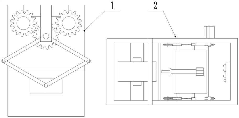
[0025] An automatic punching machine for processing drill pipe joints, comprising a punching device 1 and a blanking device 2 located on one side of the punching device 1;

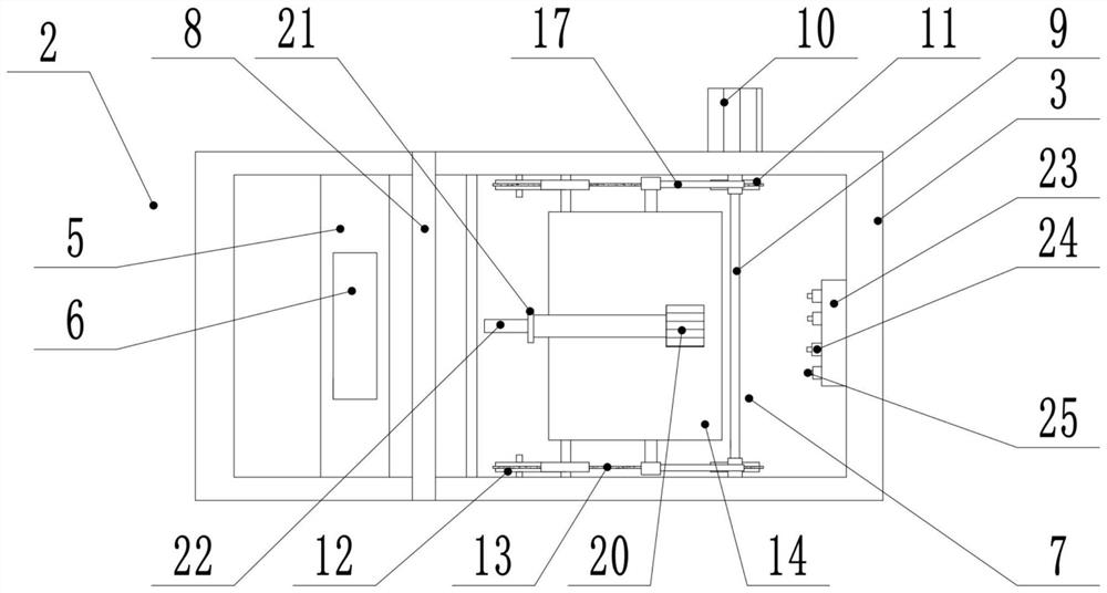
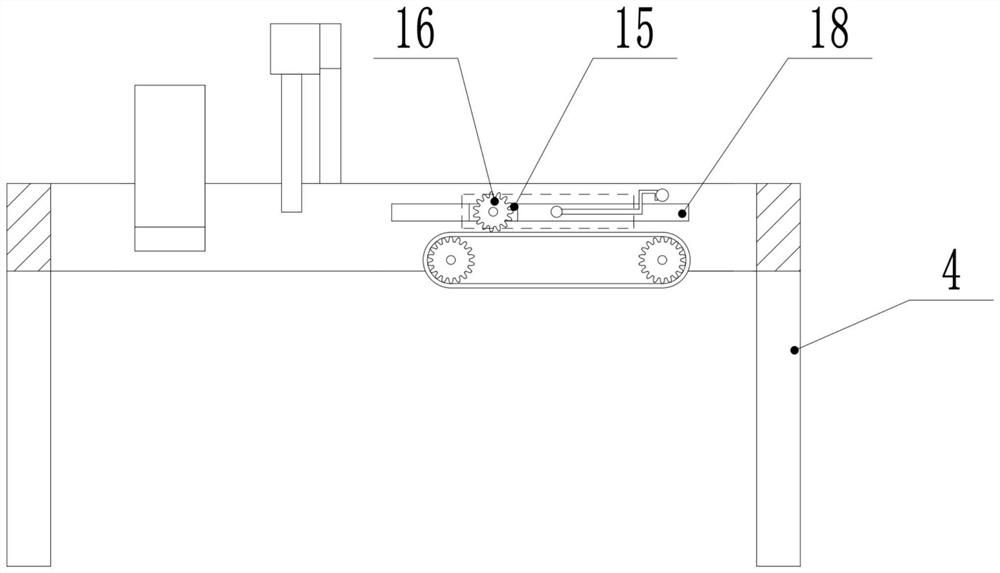
[0026] The punching device 1 comprises a work frame 3 of a frame structure, a support column 4 installed at the bottom of the work frame 3 and positioned at the four corners of the work frame 3, a support plate 5 installed on one side of the work frame 3, and a support plate 5 mounted on the support plate 5 And the support block 6 of V-shaped structure is installed on the work frame 3 and is located on the punching assembly 7 on the side of the work frame 3 away from the support plate 5, is installed on the work frame 3 and is located between the support plate 5 and the punching assembly 7 Between the first clamping assembly 8;

[0027] Punching assembly 7 comprises the ma...


PUM


Abstract

The invention discloses an automatic punching machine for drill rod joint machining. Movement is transmitted through a chain wheel and a chain, a third chain wheel is meshed with an annular chain, a workbench rotates along with the third chain wheel, a transmission block moves along a translation groove, and the workbench is turned over by 180 degrees, so that a spraying nozzle can directly spray water to a die rod for cooling conveniently, and the problem that after the die rod makes direct contact with a high-temperature drill rod joint, the mechanical performance and the deformation resistance are changed is solved. Through a discharging device, the problem that an existing punching machine depends on manual discharging is solved; a second clamping assembly is driven by a driving assembly to get close to the drill rod joint, and the direction of the drill rod joint is adjusted; a parallelogram structure with four equal sides is formed among a driving rod A, a driving rod B, a driving rod C and a driving rod D, and the parallelogram structure is deformed through gear engagement transmission, so that a vertical rod moves in parallel on the horizontal plane; and a second clamping assembly moves along with the vertical rod, so that preparation is made for clamping the drill rod joint.

Description

technical field [0001] The invention specifically relates to an automatic punching machine for processing drill pipe joints. Background technique [0002] Coal is the main solid fuel and combustible organic rock. It is formed by the luxuriant plants growing in a certain geological age, gradually accumulating into thick layers in a suitable geological environment, and buried in the bottom of the water or in the sand, and formed after a long geological age of natural coalification. Coalbed methane is a gas resource that is associated and symbiotic with coal. It refers to hydrocarbon gas stored in coal seams, with methane as the main component, and belongs to unconventional natural gas. Before coal mining, the mining and drainage of coalbed methane in the coal seam can reduce the ventilation requirements of coal mines and improve the safety production conditions of miners. [0003] Drill pipe is one of the indispensable devices in coal seam mining, and the drill pipe is gener...

Claims


Application Information

Patent Timeline
Patent Type & Authority Applications(China)
IPC IPC(8): B21D28/34B21D28/32B21D28/04B21D43/14B21D37/16
Inventor 许炳锡王辉王刚
Owner 江苏拓海煤矿钻探机械有限公司
Why Eureka
Try Eureka