Anti-icing structure suitable for aero-engine supporting plate and wing

An aero-engine and anti-icing technology, which is applied in the direction of engine components, machines/engines, aircraft parts, etc., can solve the problems of reduced engine performance, uneven protection effect, and single means

Active Publication Date: 2021-04-20
NANJING UNIV OF AERONAUTICS & ASTRONAUTICS
View PDF6 Cites 3 Cited by
  • Summary
  • Abstract
  • Description
  • Claims
  • Application Information

AI Technical Summary

Problems solved by technology

First of all, hot gas anti-icing requires bleed air from the high-pressure stage of the engine, and these gases are very valuable to the engine, and the bleed air will reduce the engine's working ability and thrust; second, it is necessary to improve the heat transfer of the thermal anti-icing system Efficiency requires complex hot gas channel design, so it is inevitable to open holes and slits inside and on the surface of the component, resulting in insufficient strength of the component; third, some components with large spans, such as wings and support plates, etc. , there is a problem of uneven protection effect when performing hot air anti-icing, and the protection effect is poor in areas far away from the hot air source; finally, the thermal anti-icing system only relies on the design of the flow structure of the hot air to complete the heat exchange, and the method is single and the space for improvement is not large. Big

Method used


Image

  • Anti-icing structure suitable for aero-engine supporting plate and wing
  • Anti-icing structure suitable for aero-engine supporting plate and wing
  • Anti-icing structure suitable for aero-engine supporting plate and wing

Examples


Embodiment Construction

[0018] The present invention will be further described in detail below in conjunction with specific implementation methods and accompanying drawings.

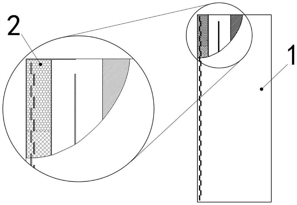
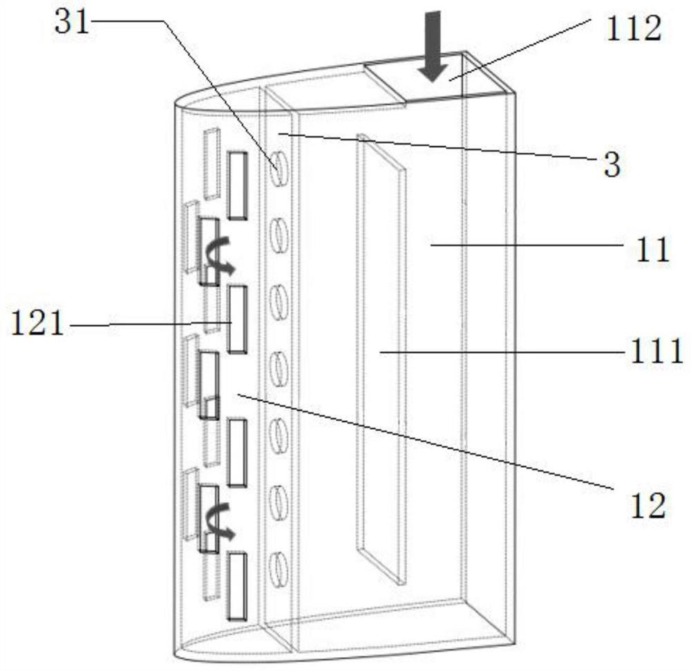
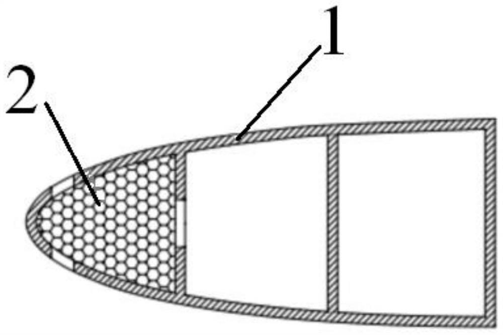
[0019] Such as figure 1 with figure 2 As shown, the present invention includes an anti-icing component 1 with a three-dimensional full-scale structure, and the material of the anti-icing component 1 is aluminum. A partition 3 is arranged inside the anti-icing component 1, and the partition 3 divides the internal space of the anti-icing component 1 into left and right parts. A plurality of jet holes 31 are set on the partition 3, and parameters such as impact distance, hole shape, hole size, hole spacing, and opening angle are adjusted for the jet holes 31 according to heat flow conditions and component sizes. In this embodiment, the jet holes 31 are circular and arranged in a single row with equal intervals. The air intake chamber 11 and the impingement chamber 12 communicate through the jet hole 31 , forming a convective-i...


PUM


Abstract

The invention discloses an anti-icing structure suitable for an aero-engine flow rectifing supporting plate and a wing. The anti-icing structure comprises an anti-icing part, a partition plate is arranged in the anti-icing part and divides the inner space of the anti-icing part into an air inlet cavity and an impact cavity, a jet hole is formed in the partition plate, the air inlet cavity and the impact cavity communicates through the jet hole, and convection-impact heat exchange of heat flow between the air inlet cavity and the impact cavity is formed; a flow dividing plate is vertically arranged in the air inlet cavity, an air inlet is formed in the top of the air inlet cavity on the right side of the flow dividing plate, and gaps are reserved between the two ends of the flow dividing plate and the top face and the bottom face of the anti-icing part to form a heat flow forward conveying channel; and a plurality of layers of porous medium fillers are laid in the impact cavity in the unfolding direction, and air outlet slits are formed in the surface of the impact cavity. Heat flow distribution away from the far end and the near end of a heat source can be regulated and controlled, non-uniform protection of the far end and the near end of a traditional heat exchange structure is reduced, the heat exchange effect of hot air flow and the front edge of a part can be enhanced, and hot air condition requirements needed by a conventional hot air anti-icing method are reduced.

Description

technical field [0001] The invention relates to an anti-icing heat transfer technology for aircraft components, in particular to an anti-icing structure suitable for aeroengine support plates and wings. Background technique [0002] When an aircraft flies in a high-altitude, low-temperature, and humid environment, ice will accumulate on the surface of some windward components, such as wings and leading edges of straightening struts. The generation of icing not only affects the working performance of the aircraft, but also seriously threatens the flight safety. At present, the anti-icing method of most parts on the aircraft is implemented in the form of hot gas anti-icing. This anti-icing method is mature and widely used, but it also has some disadvantages. First of all, hot gas anti-icing requires bleed air from the high-pressure stage of the engine, and these gases are very valuable to the engine, and the bleed air will reduce the engine's working ability and thrust; secon...

Claims


Application Information

Patent Timeline
Patent Type & Authority Applications(China)
IPC IPC(8): F02C7/047F01D25/02F01D25/10B64D15/04
Inventor 宣益民梁久立连文磊
Owner NANJING UNIV OF AERONAUTICS & ASTRONAUTICS
Why Eureka
Try Eureka