Method for improving tracking precision of photoelectric tracking system
A technology of photoelectric tracking system and tracking accuracy, which is applied in the direction of using feedback control, etc., can solve the problems of time lag of off-target information, reduction of phase margin of tracking control system, and influence of tracking accuracy of photoelectric tracking system, so as to improve accuracy and stability performance, and the effect of improving accuracy
- Summary
- Abstract
- Description
- Claims
- Application Information
AI Technical Summary
Problems solved by technology
Method used
Image
Examples
Embodiment 1
[0042] Embodiment 1: A photoelectric tracking control system, see attached figure 1 , which includes a speed inner loop controller, a position outer loop controller, and a TV tracker; in the figure, G 0 (s) transfer function for the control object, G vc (s), G pc (s) and G TV (s) are the transfer functions of the speed inner loop controller, the position outer loop controller and the TV tracker respectively, θ i , θ o and Δθ are the target position, the angle value of the photoelectric tracking system, and the miss amount obtained by the TV tracker, respectively. The relationship between the target position, the angle value of the photoelectric tracking system, and the amount of misses obtained by the TV tracker is expressed as:
[0043] Δθ=(θ i -θ o )G TV (s) (1)
[0044] G TV (s)=Re -τs (2)
[0045] Among them, K is the equivalent of the TV tracker, τ is the lag time, and its frequency characteristics can be expressed as
[0046]
[0047] Through the analysi...
Embodiment 2
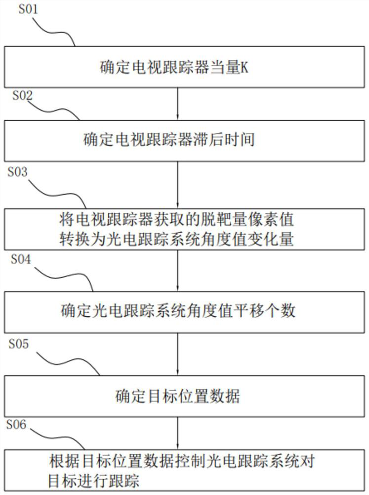
[0048] Embodiment 2: A method for improving the tracking accuracy of the photoelectric tracking system, see the attached figure 2 , including the following steps:
[0049] S01. Determine the TV tracker equivalent K;
[0050] S02. Determine the lag time τ of the TV tracker;
[0051] S03. The pixel value Δθ of the off-target amount acquired by the TV tracker n Converted to miss angle value dθ n , where n is a positive integer;
[0052] S04. Determine the angle value θ of the photoelectric tracking system o,n Number of shifts N; where T 1 is the instrument data sampling interval;
[0053] S05. Determine the target position data θ i,n-N , θ i,n-N =dθ n +θ o,n-N ;
[0054] S06. Control the photoelectric tracking system to track the target according to the target position data.
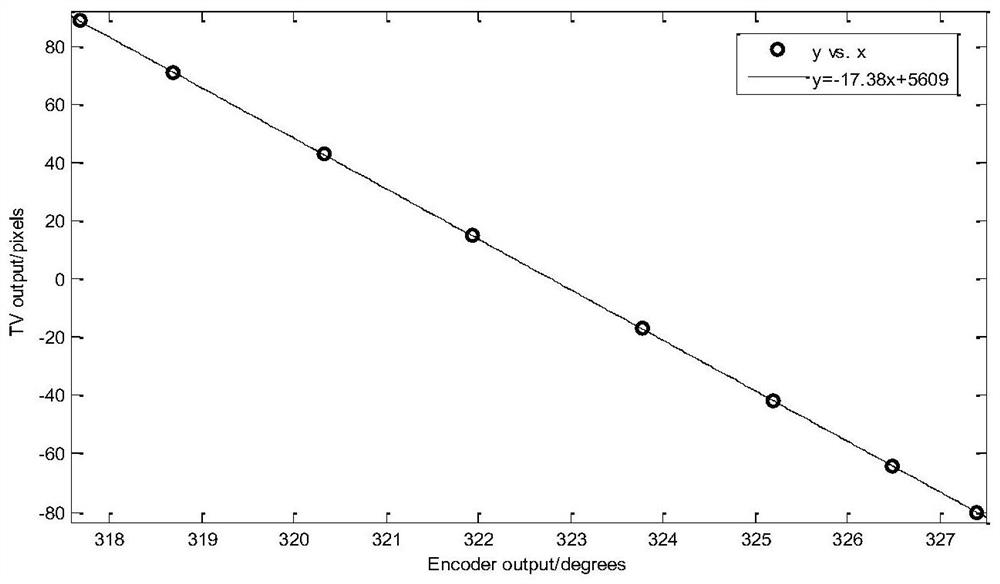
[0055] First determine the TV tracker equivalent K and TV tracker lag time τ in the photoelectric tracking system, and then determine the target position data in the subsequent steps, throu...
Embodiment 3
[0076] Embodiment three, a kind of photoelectric tracking system test equipment, refer to the attached Figure 7 , including a rotating target 1, which rotates in a vertical plane, an LED light 2 as a tracked target is arranged on the rotating target 1, and the LDE light is fixed on the edge of the rotating target 1; Lamp 2 is tracked, adopts the method of embodiment two, uses target speed data as feed-forward to track LED lamp 2, Figure 8-11 Corresponding to the target speed prediction of frame 0, frame 1, frame 2 and frame 3 respectively, in each figure, the upper figure is the comparison curve of the tracking error when using traditional feedback control and when the target speed data is used as feedforward, The figure below is the feedforward speed curve obtained by predictive filtering; in the figure above, the dotted line is the tracking error curve when using traditional feedback control, and the solid line is the tracking error curve when the target speed data is used...
PUM
 Abstract
Description
Claims
Application Information
 - R&D
- Intellectual Property
- Life Sciences
- Materials
- Tech Scout
- Unparalleled Data Quality
- Higher Quality Content
- 60% Fewer Hallucinations
Browse by: Latest US Patents, China's latest patents, Technical Efficacy Thesaurus, Application Domain, Technology Topic, Popular Technical Reports.
© 2025 PatSnap. All rights reserved.Legal|Privacy policy|Modern Slavery Act Transparency Statement|Sitemap|About US| Contact US: help@patsnap.com


