Forge piece adjusting method based on three-dimensional scanning auxiliary positioning
An auxiliary positioning and three-dimensional scanning technology, applied in image data processing, 3D modeling, instruments, etc., can solve problems such as inability to connect organically, and achieve the effect of reducing the difficulty of calibration, shortening the production cycle, and clear calibration results
- Summary
- Abstract
- Description
- Claims
- Application Information
AI Technical Summary
Problems solved by technology
Method used
Image

Examples
Embodiment 1
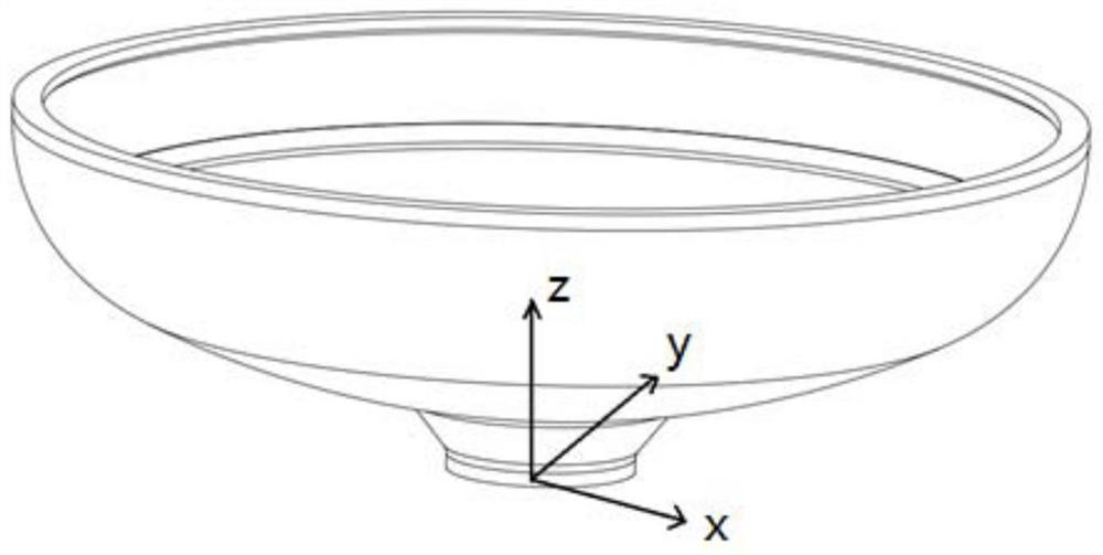
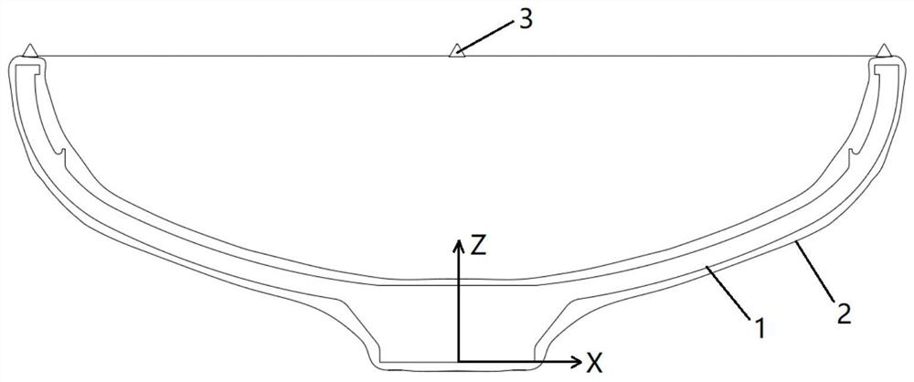
[0048] Embodiment 1, reference Figure 1 to Figure 3 :
[0049] A large "bowl-shaped" part, which is shaped like a bowl, and the diameter of the "bowl mouth" and "bowl bottom" is quite different. When measuring on a vertical lathe, in order to ensure that the inside and outside can be measured at the same station, it is necessary to Keep the "bowl mouth" facing up and place it on the machine tool. At the same time, perform operations such as padding and clamping on the "bowl bottom" part. The calibration of this part is mainly for the "bowl mouth" position.
[0050] S1 model acquisition:
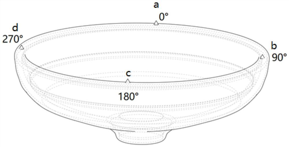
[0051] S10 According to the principle of "three points can locate the spatial position of an object", the feature points should not be less than three points, and the feature points should be distributed as evenly and symmetrically as possible, and each feature point should be representative and not repeated. If the feature points are collected in a small area of the object, the correspo...
Embodiment 2
[0067] Embodiment 2, refer to Figure 4 :
[0068] A large thin-walled steel pipe. When the allowance is small, it is necessary to take into account the allowance of the inner circle before machining the outer circle on the horizontal lathe to determine the axis of the part. Now it is planned to use the milling machine to process the reference holes at both ends to determine the axis of the part, and it is necessary to correct the part on the workbench before processing.
[0069] Steps S1 and S2 are similar to Embodiment 1, and will not be repeated here. Note that feature point b and feature point c should be set in the same tectonic quadrant as much as possible at this time, so as to reduce the interactive influence of subsequent adjustments. In this embodiment, the feature Point b and feature point c are set in the x-z quadrant.
[0070] S3 confirms calibration:
[0071] The steel pipe part uses a three-dimensional coordinate comparison, that is, ΔX, ΔY, and ΔZ in the cor...
Embodiment 3
[0076] Embodiment 3, refer to Figure 5-Figure 7 :
[0077] Such as Figure 5 As shown, a plate-shaped part, three feature points a, b, c are set on the upper surface, and the feature points are at Image 6 The three-dimensional coordinates in the coordinate system of the standard model shown are a(X 1 , Y 1 ,Z 1 ), b(X 2 , Y 2 ,Z 2 ), c(X 3 , Y 3 ,Z 3 ).
[0078] Place the part blank on the machine tool table to obtain the three-dimensional coordinates a(X 1 '', Y 1 '',Z 1 ''), b(X 2 '', Y 2 '',Z 2 ''), c(X 3 '', Y 3 '',Z 3 '').
[0079] The Z-axis coordinate Z of each feature point is the vertical distance from the feature point to the X-Y plane. When the part blank has different horizontal states in the two coordinate systems, the corresponding Z-axis coordinate difference (Z 1-2 ,Z 1-3 ) and (Z 1-2 '',Z 1-3 '') vary. Therefore, the horizontal adjustment is performed first, and the Z-axis coordinate difference (Z 1-2 '',Z 1-3 '') adjusted to the af...
PUM
 Abstract
Description
Claims
Application Information
 - R&D
- Intellectual Property
- Life Sciences
- Materials
- Tech Scout
- Unparalleled Data Quality
- Higher Quality Content
- 60% Fewer Hallucinations
Browse by: Latest US Patents, China's latest patents, Technical Efficacy Thesaurus, Application Domain, Technology Topic, Popular Technical Reports.
© 2025 PatSnap. All rights reserved.Legal|Privacy policy|Modern Slavery Act Transparency Statement|Sitemap|About US| Contact US: help@patsnap.com