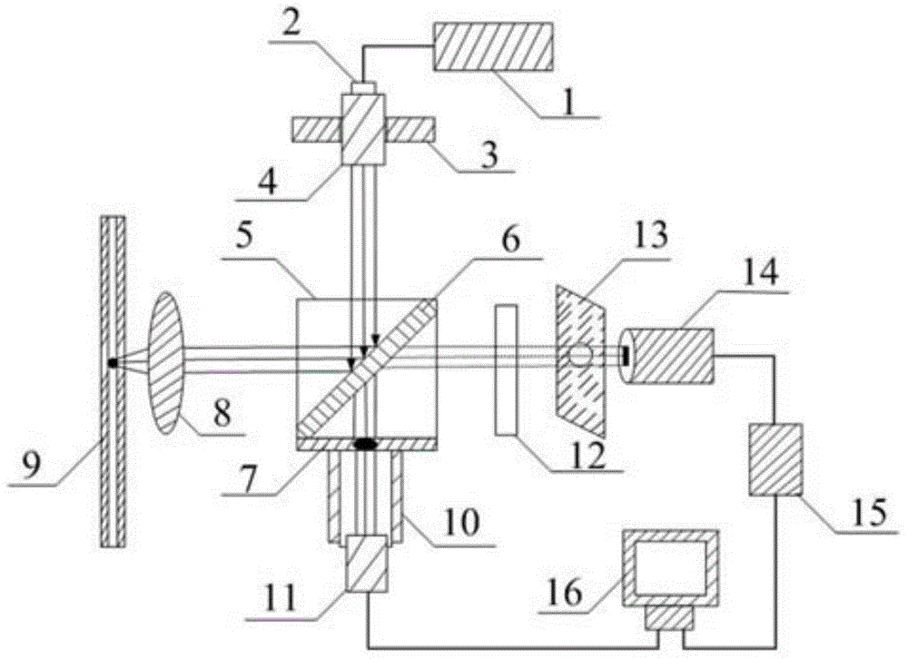
Visualization calibration laser-induced fluorescence detection device
A technology of laser-induced fluorescence and detection equipment, which is applied in the direction of fluorescence/phosphorescence, material excitation analysis, etc. It can solve the problems of optical path deviation, prolonged operation time, and difficulty in distinguishing the position with the highest brightness, so as to achieve the collimation of laser incident light , Reduce the difficulty of calibration, improve the applicability and stability
- Summary
- Abstract
- Description
- Claims
- Application Information
AI Technical Summary
Problems solved by technology
Method used
Image

Examples
experiment example
[0040] Experimental example: Calibrate the 473nm wavelength laser and use it to detect fluorescein isothiocyanate (FITC).
[0041] Experimental conditions:
[0042] Laser: 473nm solid-state laser (fiber output)
[0043] Dichroic mirror: ZT488rdc;
[0044] Emission filter: ET525 / 50m;
[0045] Hollow quartz capillary tube: 100μm I.D.*360μm 0.D.*130 cm long;
[0046] Mobile phase: methanol;
[0047] Injection volume: 10μL.
[0048] Pump flow rate: 0.5mL / min;
[0049] Sample: 5×10⁻⁶~5×10-12 mol / L FITC;
[0050] The calibration process is as Figure 8 with Picture 9 As shown, Figure 8 Change the laser wavelength to 473nm, the corresponding dichroic mirror and divergent filter set module will cause the deviation of the optical path system, and then fine-tune the two-dimensional adjustment device for calibration. The calibration result is as follows Picture 9 Shown.
[0051] Picture 10 In order to calibrate the chromatogram of the fluorescence test, after calibration, the instrument performance ...
PUM
 Abstract
Description
Claims
Application Information
 - R&D
- Intellectual Property
- Life Sciences
- Materials
- Tech Scout
- Unparalleled Data Quality
- Higher Quality Content
- 60% Fewer Hallucinations
Browse by: Latest US Patents, China's latest patents, Technical Efficacy Thesaurus, Application Domain, Technology Topic, Popular Technical Reports.
© 2025 PatSnap. All rights reserved.Legal|Privacy policy|Modern Slavery Act Transparency Statement|Sitemap|About US| Contact US: help@patsnap.com