Wire harness management device for slip ring-free solar wing driving mechanism

A solar wing drive and management device technology, applied in the aerospace field, can solve problems such as large resistance torque, damage to cable insulation, short circuit, etc., and achieve the effects of reduced pressing force requirements, reduced risk of damage, and flexible use scenarios

Active Publication Date: 2021-04-20
CHANGGUANG SATELLITE TECH CO LTD
View PDF8 Cites 3 Cited by
  • Summary
  • Abstract
  • Description
  • Claims
  • Application Information

AI Technical Summary

Problems solved by technology

The above-mentioned patent uses a wire card and a wire harness box to solve the torsion of the cable, but because all the cables are twisted into one strand, the wire harness itself is bloated, and the wire card needs a lot of force to fix the wire harness. The force is easy to pinch the cable or damage the insulation of the cable, resulting in a short circuit
Moreover, a single thicker wire harness will generate a larger resistance moment when twisted, and there will be more intense friction between the cables, which will increase the risk of short circuits caused by abrasion of the insulation of the cables to a certain extent.
Another disadvantage of the single thicker wire harness scheme is that its rotation angle is small, which is determined by its own bulkiness, which will lead to its poor applicability and cannot meet the requirements of large-angle rotation

Method used


Image

  • Wire harness management device for slip ring-free solar wing driving mechanism
  • Wire harness management device for slip ring-free solar wing driving mechanism
  • Wire harness management device for slip ring-free solar wing driving mechanism

Examples


Embodiment Construction

[0043] In order to enable those skilled in the art to better understand the technical solutions of the present invention, the present invention will be further described in detail below in conjunction with the accompanying drawings.

[0044] see Figure 2 to Figure 5 shown;

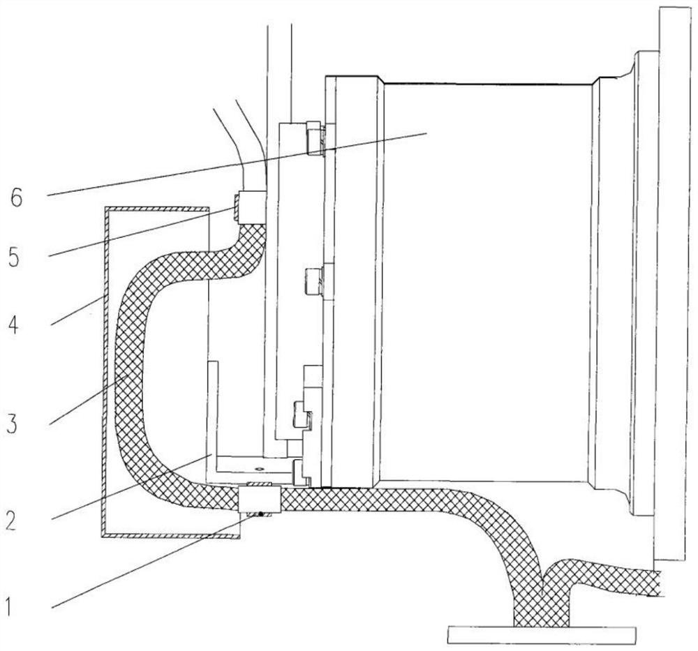
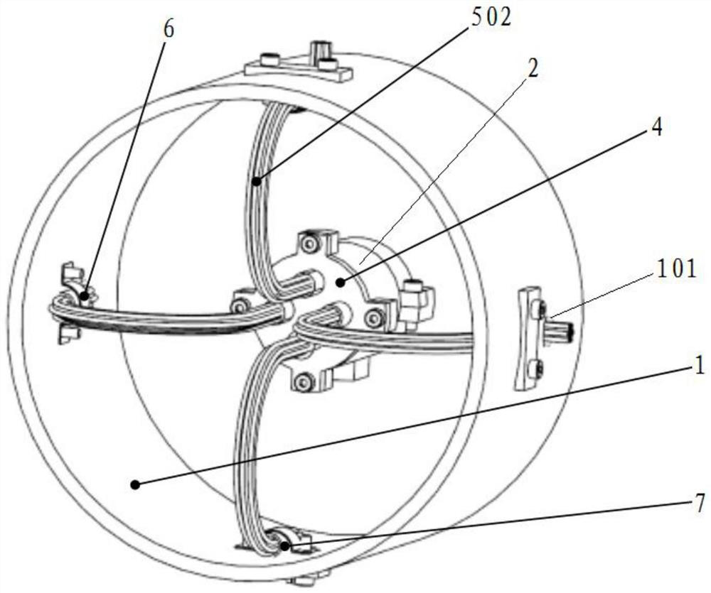
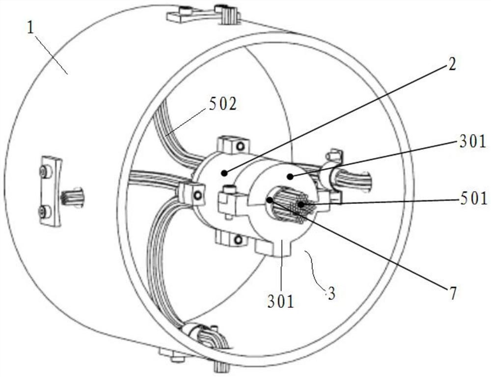
[0045] A wire harness management device for a non-slip ring solar wing drive mechanism of the present invention, the device is used for wire harness storage, and the device includes:

[0046] A box body 1, the box body 1 has a cylindrical structure, and the inside of the box body 1 is hollowly formed as an accommodating cavity;

[0047] The wire harness fixing sleeve 2 integrated in the accommodation cavity of the box body 1;

[0048] One end of the wire harness fixing sleeve 2 is integrated with a wire harness compression sleeve 3, and the end of the wire harness fixing sleeve 2 away from the wire harness compression sleeve 3 is integrated with a wire splitter 4;

[0049] The matching position of the ...


PUM


Abstract

The invention discloses a wire harness management device for a slip ring-free solar wing driving mechanism. The wire harness management device comprises a box body and a wire harness fixing sleeve integrated in an accommodating cavity of the box body, the matching position of the wire harness and one end of a wire harness pressing sleeve is configured to be a whole wire harness, and the whole wire harness of the wire harness is divided into four strands of branch wire harnesses through a deconcentrator; branch wire harness leading-out holes are distributed in the box body in the circumferential direction of the box body. Part of the branch wire harness is contained in the accommodating cavity, and the far end of the branch wire harness is led out of the branch wire harness lead-out hole. According to the device, the whole wire harness is divided into four strands of branch wire harnesses, the bloating property of the wire harness is greatly reduced, the resistance moment corresponding to a single strand of wire harness is greatly reduced due to the fact that the wire harness is thinned, the requirement for the pressing force of the wire harness fixing sleeve is also reduced, and therefore the risk that a cable at the fixed end of the wire harness is damaged is reduced; in addition, the torsion property of the wire harness can be improved, so that the rotation angle of the wire harness management device is increased, and the applicability of the wire harness management device to different wire harness management requirements is improved.

Description

technical field [0001] The invention relates to the technical field of aerospace technology, in particular to a wire harness management device for a non-slip ring solar wing drive mechanism. Background technique [0002] The solar wing driving mechanism is a very important moving part on the satellite. Its main function is to drive the solar wing to rotate, so that the plane normal of the solar cells coincides with the solar beam, so as to obtain as much solar energy as possible. It is also the energy and signal exchange channel between the interior of the satellite and the solar wing, and the power line and signal line on the star need to pass through the solar wing drive mechanism. As a rotatable device with multiple cables passing through at the same time, Xu Ya of the solar wing drive mechanism balances the contradiction between "the device needs to rotate" and "the cable is not easy to twist". The traditional solar wing drive mechanism uses conductive sliding To solve ...

Claims


Application Information

Patent Timeline
Patent Type & Authority Applications(China)
IPC IPC(8): H02G3/08H02G3/04
CPCY02T50/50
Inventor 李佳乐张道威谷松臧宏达赵春娟程浩于济菘赵相禹关永亮于航
Owner CHANGGUANG SATELLITE TECH CO LTD
Why Eureka
Try Eureka