Non-contact sensor switch based on Hall and logic magnetic coding technology

A non-contact, magnetic encoding technology, which is applied in electronic switches, pulse technology, relays, etc., can solve the problem of low confidentiality level of magnetic encoding sensors, and achieve the effect of capturing signals at a good position, high electromagnetic compatibility, and ensuring equipment safety

Pending Publication Date: 2021-04-20
SUNS ELECTRIC ZHANGZHOU
View PDF0 Cites 0 Cited by
  • Summary
  • Abstract
  • Description
  • Claims
  • Application Information

AI Technical Summary

Problems solved by technology

For example, the IDEM brand magnetic code interlock switch of the European Community does not form a logical operation relationship with the three Hall elements used. One of the switches can easily trigger the action with only a single magnet, although the other two Hall elements form a It is related to logic, but because the number is too small and only two Hall elements, the sensor can also be triggered by the north and south poles of a magnet at the same time, so the magnetic coded sensor of this brand has a low level of confidentiality

Method used


Image

  • Non-contact sensor switch based on Hall and logic magnetic coding technology
  • Non-contact sensor switch based on Hall and logic magnetic coding technology

Examples


Embodiment 1

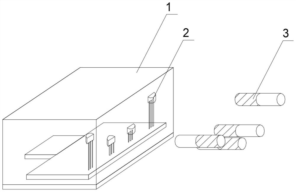
[0024] refer to figure 1 , a non-contact sensor switch based on Hall and logic magnetic encoding technology, including a non-contact sensor circuit and its packaging shell 1, the non-contact sensor circuit includes a relay, the relay includes a control coil input terminal and normally open and normally open Closed contact output terminal, the non-contact sensor circuit controls the relay to be turned on or off through an AND operation logic circuit and a NOT gate circuit based on N single-stage Hall elements 2, and the AND logic operation circuit passes The N single-stage Hall elements 2 form a logic magnetic code according to the magnetic pole direction, position and quantity, and the input end of the AND logic operation circuit is provided with a power input polarity protection circuit.

[0025] While working, refer to figure 1 After encapsulating the sensor switch through the shell 1, use the same number as the single-stage Hall element 2, and the magnet 3 corresponding to...

Embodiment 2

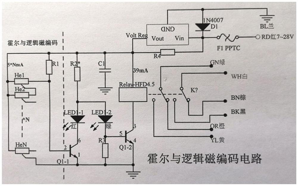
[0027] refer to figure 2 , a non-contact sensor circuit, the non-contact sensor circuit includes a single-stage Hall element He, a composite transistor Q1-1, a composite transistor Q1-2, a pull-up resistor R1, a pull-up resistor R2, a pull-down resistor R3, a filter capacitor C1, Diode D1, self-recovery insurance device F1, voltage regulator; the self-recovery insurance device F1 and diode D1 form a power supply input polarity protection circuit, and current limiting protection is performed through the voltage regulator; the NOT gate circuit is composed of the The composite transistor Q1-1 and the composite transistor Q1-2 are composed, the base of the composite transistor Q1-1 is connected to the pull-up resistor R1, and the base of the composite transistor Q1-2 is connected to the pull-down resistor R3 , the collector of the composite transistor Q1-1 and the base of the composite transistor Q1-2 are connected to the pull-up resistor R2, the emitter of the composite transist...


PUM


Abstract

The invention relates to a non-contact sensor switch based on Hall and logic magnetic coding technology, which comprises a non-contact sensor circuit and a packaging shell thereof, the non-contact sensor circuit comprises a relay, the relay comprises an input end and an output end, the contactless sensor circuit controls the relay to realize conduction or blocking through an AND logic operation circuit and a NOT gate circuit which are formed based on N single-stage Hall elements, and the AND logic operation circuit forms a logic magnetic password through the N single-stage Hall elements according to the direction, position and number of magnetic poles. The open-drain output characteristics of only one pull-up resistor and a plurality of single-pole non-latch Hall elements are shared, logic magnetic codes are formed through the magnetic pole directions, the positions and the number of the single-pole non-latch Hall elements, magnetic coding of the relation between self-composition and logic operation of the multiple Hall elements is achieved, and the purposes of being small, stable, reliable, rapid and convenient are achieved.

Description

technical field [0001] The invention relates to the field of sensor switches, in particular to a non-contact sensor switch based on Hall and logic magnetic encoding technology. Background technique [0002] The Hall effect was discovered by the American physicist Hall in 1879 when he was studying the mechanism of metal conduction: an external magnetic field perpendicular to the conductor current can cause a potential difference at both ends of the conductor current direction. This phenomenon is called the Hall effect. The application of the Hall effect is mostly used in the field of switches. Because the Hall sensor has the characteristics of non-contact, it can be used in some switches that require airtightness, waterproof, and extended life, especially in gear switches. Rotate to trigger the Hall sensors in different gears to enable the functions of different gears. [0003] Hall components need to be in close contact with the magnetic induction corresponding to the magne...

Claims


Application Information

Patent Timeline
IPC IPC(8): H03K17/95H01H47/00
Inventor 叶帆齐铭宇
Owner SUNS ELECTRIC ZHANGZHOU
Why Eureka
Try Eureka