Cleaning and maintaining mechanism for medical apparatus and instruments

A technology of medical equipment and discharge mechanism, applied in the field of medical equipment, can solve the problems of high labor intensity, low efficiency, manual cleaning, scratch infection, cleaning efficiency, etc.

Active Publication Date: 2021-04-23
QINGDAO MUNICIPAL HOSPITAL
View PDF4 Cites 1 Cited by
  • Summary
  • Abstract
  • Description
  • Claims
  • Application Information

AI Technical Summary

Problems solved by technology

[0004] Aiming at the deficiencies of the prior art, the present invention provides a cleaning and maintenance mechanism for medical equi

Method used


Image

  • Cleaning and maintaining mechanism for medical apparatus and instruments
  • Cleaning and maintaining mechanism for medical apparatus and instruments
  • Cleaning and maintaining mechanism for medical apparatus and instruments

Examples


Embodiment 1

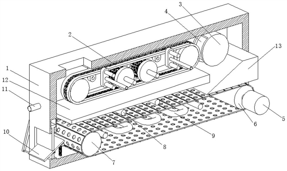
[0030] A cleaning and maintenance mechanism for medical equipment, such as Figure 1-Figure 5 As shown, the box body 1 is included, the inside of the box body 1 is provided with a cleaning mechanism 2, the top wall inside the box body 1 is welded with a casing 3, the inner wall of the casing 3 is rotatably connected with a magnet 4, and the right side of the box body 1 is provided with a transmission Mechanism 5, the inner wall of the box body 1 is respectively connected to the driving roller 6 and the driven roller 7, and the driven roller 7 is located at the front of the driving roller 6, and the surface of the driving roller 6 is connected to the surface of the driven roller 7 through a conveyor belt. The inner wall of the box body 1 is fixedly connected with an ultraviolet lamp 8 and a heating tube 9 respectively, and the ultraviolet lamp 8 and the heating tube 9 are located between the driven drum 7 and the driving drum 6, and the ultraviolet lamp 8 is located above the he...

Embodiment 2

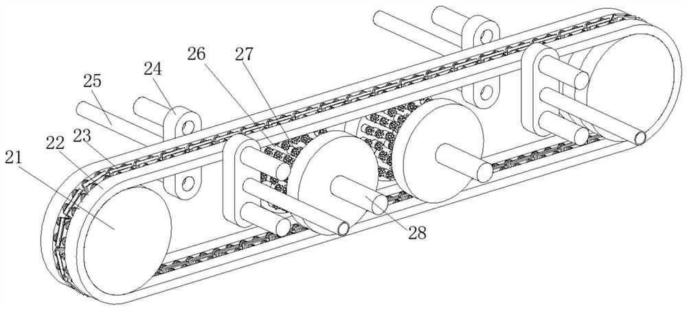
[0039] Such as Figure 5-Figure 7 As shown, on the basis of Embodiment 1, in this embodiment, the left side of the motor 51 is connected to the right side of the box body 1 by bolts, and the output end of the motor 51 is clamped and fixed with the shaft center of the drive roller 6. The axle center of No. belt pulley 53 is clamped and fixed by the axle center of connecting rod and magnet 4, and the axle center of No. three pulley 56 is clamped and fixed by the axle center of connecting rod and sprocket wheel 21, double-layer pulley 57 and four The axle center of No. belt pulley 58 is welded and fixed with the left end of two rotating shafts 28 respectively, and the surface of No. 1 gear 54 and No. 2 gear 55 is provided with through hole, can reduce the material needed during manufacture, and then reduce cost and input, and also Its weight can be reduced, it is convenient to install and maintain it in a subsequent sequence, and it has high practicability.

[0040] The discharg...


PUM


Abstract

The invention relates to the technical field of medical apparatus and instruments, and discloses a cleaning and maintaining mechanism for medical apparatus and instruments. The cleaning and maintaining mechanism for the medical apparatus and instruments comprises a box body, a cleaning mechanism is arranged in the box body, a shell is welded to the top wall in the box body, a magnet is rotatably connected to the inner wall of the shell, and a transmission mechanism is arranged on the right side of the box body. A transmission roller and a driven roller are rotationally connected to the inner wall of the box body, an ultraviolet lamp and a heating pipe are fixedly connected to the inner wall of the box body, a discharging mechanism is arranged on the front portion of the box body, and an inclined plate and an inclined block are welded to the inner wall of the box body. According to the cleaning and maintaining mechanism for the medical apparatus and instruments, scalpels and operating forceps can be automatically cleaned through the cleaning mechanism and the transmission mechanism, manual cleaning is not needed, the risk that the scalpels and the operating forceps are scratched by apparatus and instruments is reduced, the safety is high, the labor intensity of medical staff is reduced, and the cleaned medical apparatus and instruments can be dried and disinfected through the ultraviolet lamp and the heating pipe, thus integration of cleaning, drying and disinfecting is achieved.

Description

technical field [0001] The invention relates to the technical field of medical devices, in particular to a cleaning and maintenance mechanism for medical devices. Background technique [0002] Medical devices refer to instruments, equipment, utensils, in vitro diagnostic reagents and calibrators, materials, and other similar or related items that are directly or indirectly used on the human body, including the required computer software. The utility is mainly obtained through physical means, not through Obtained by means of pharmacology, immunology or metabolism, or although these methods are involved but only play an auxiliary role, the purpose is diagnosis, prevention, monitoring, treatment or alleviation of disease; diagnosis, monitoring, treatment, alleviation or functional compensation of injury; The inspection, replacement, regulation, or support of a physiological structure or process. [0003] At present, medical devices in the market need to be cleaned manually, su...

Claims


Application Information

Patent Timeline
IPC IPC(8): B08B1/02B08B3/02B08B13/00F26B15/18F26B23/00F26B25/00A61L2/10
Inventor 王代分
Owner QINGDAO MUNICIPAL HOSPITAL
Why Eureka
Try Eureka