
Method, system and medium for identifying air-film hole penetration area using high-speed camera

A high-speed camera and air film hole technology, which is used in metal processing equipment, welding equipment, manufacturing tools, etc., can solve the problems of inability to accurately determine the exact time of turbine blades, cleaning of filling materials, and inability to fill protective materials.

Active Publication Date: 2022-07-15
XIAN MICROMACH TECH CO LTD
View PDF7 Cites 0 Cited by
  • Summary
  • Abstract
  • Description
  • Claims
  • Application Information

AI Technical Summary

Problems solved by technology

However, the related technology has the following defects: First, the human eye can visually distinguish pictures at a limit of 30 frames per second, and what is collected by an industrial CCD camera is a continuous video, and the accuracy of the turbine blade penetration area cannot be accurately determined by human eyes. Second, the structure of the cavity of the turbine blade is complex, and there will be problems such as insufficient filling or cleaning of the filling material after processing; then, the sealed cavity of the turbine blade with a small wall-to-wall distance cannot be filled with protective materials

Method used


Image

  • Method, system and medium for identifying air-film hole penetration area using high-speed camera
  • Method, system and medium for identifying air-film hole penetration area using high-speed camera
  • Method, system and medium for identifying air-film hole penetration area using high-speed camera

Examples


Embodiment Construction

[0035] The technical solutions in the embodiments of the present invention will be clearly and completely described below with reference to the accompanying drawings in the embodiments of the present invention.

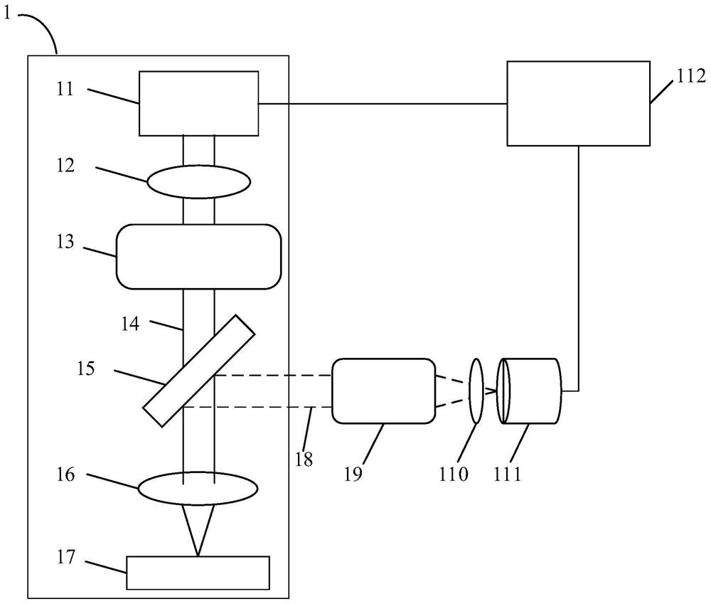
[0036] see figure 1 , which shows a laser processing equipment 1 capable of implementing the technical solutions of the embodiments of the present invention, such as figure 1 As shown, in the laser processing equipment 1, the laser beam generated by the laser 11 passes through the laser shaping part 12 and the rotary cutting scanning module 13 and then irradiates the beam splitter 15 to form the processing optical path 14; wherein, the laser shaping part 12 can make The laser beam is more uniform, and the beam expansion rate of the laser beam can also be controlled; the rotary scanning module 13 can make the laser beam irradiate according to the set processing optical path 14; the beam splitter 105 transmits the laser beam in the processing optical path 14 to the focu...


PUM


Abstract

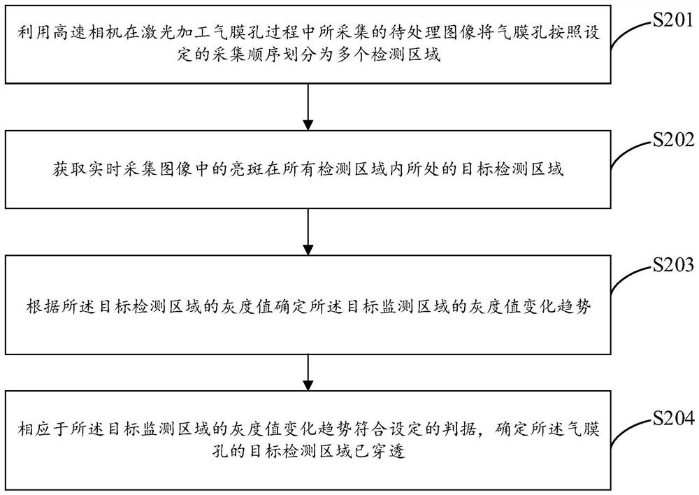
The embodiment of the invention discloses a method, system and medium for identifying the penetration area of ​​a gas film hole by using a high-speed camera; the method includes: using a to-be-processed image collected by the high-speed camera in the process of laser processing the gas film hole to identify the gas film hole Divide into multiple detection areas according to the set acquisition sequence; obtain the target detection area where the bright spot in the real-time acquisition image is located in all detection areas; determine the target detection area according to the gray value of the target detection area The gray value change trend; corresponding to the gray value change trend of the target monitoring area meeting the set criterion, it is determined that the target detection area of ​​the gas membrane hole has penetrated.

Description

technical field [0001] The embodiments of the present invention relate to the technical field of laser processing, and in particular, to a method, a system and a medium for identifying the penetration area of ​​a gas film hole by using a high-speed camera. Background technique [0002] Laser beam machining (LBM, Laser Beam Machining) technology is the most common processing technology in laser applications, and has been widely used in important national economic fields such as microelectronics, automobiles, aerospace, and machinery manufacturing. Laser processing technologies include laser cutting, laser welding, laser drilling, and micromachining. [0003] At present, the cooling technology of aero-engine turbine blades adopts external film cooling technology. The external air film cooling technology is to use laser processing technology to process one or several rows of tiny holes on the wall of the turbine blade. The cold air released inside the turbine blade flows out t...

Claims


Application Information

Patent Timeline
Patent Type & Authority Patents(China)
IPC IPC(8): B23K26/382B23K26/70
CPCB23K26/382B23K26/70B23K26/702
Inventor 刘慧安王自杨康张宝马瑞
Owner XIAN MICROMACH TECH CO LTD
Learn More