
Permanent magnet outer rotor submersible electric pump

A technology of submersible electric pump and outer rotor, applied in the direction of magnetic circuit rotating parts, pump, magnetic circuit, etc., can solve the problems of large water friction loss, low efficiency of submersible electric pump unit, and reduced insulation thickness.

Active Publication Date: 2021-04-23
HEFEI HENGDAJIANGHAI PUMP IND CO LTD
View PDF4 Cites 0 Cited by
  • Summary
  • Abstract
  • Description
  • Claims
  • Application Information

AI Technical Summary

Problems solved by technology

[0003] The purpose of the present invention is to solve the problem of low efficiency of the submersible pump unit due to the large volume of the rotor and the large water friction loss caused by the rotation in the water of the existing submersible electric pump, and propose a permanent magnet external rotor Submersible electric pump; with the reduction of the diameter of the rotor, the water friction loss is greatly reduced, and the water friction loss is proportional to the fifth power of the outer circumference, thereby greatly improving the efficiency of the unit. The stator winding adopts enamelled round copper loose wire Compared with the original water-resistant winding wire, the insulation thickness is greatly reduced, thereby increasing the power density of the stator, reducing the volume of the unit, and saving metal consumption. The windings at both ends of the stator adopt insulating glue potting technology to ensure the motor in water. Safe operation, the rotor of the motor adopts permanent magnet magnetic steel structure, which improves the performance of the motor and increases the power density of the motor; the part of the stator winding protruding from the core end is cured with insulating glue and solidified into a ring shape. The inner diameter of the ring, There are 3 ring-shaped passages on the outer diameter respectively, which facilitate water flow through the ring-shaped passages and achieve the purpose of heat dissipation and cooling at the end of the motor winding.

Method used


Image

  • Permanent magnet outer rotor submersible electric pump
  • Permanent magnet outer rotor submersible electric pump
  • Permanent magnet outer rotor submersible electric pump

Examples


Embodiment Construction

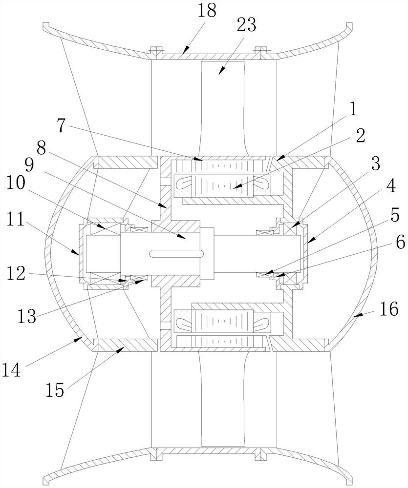
[0024] The technical solutions of the present invention will be clearly and completely described below in conjunction with the embodiments. Apparently, the described embodiments are only some of the embodiments of the present invention, not all of them. Based on the embodiments of the present invention, all other embodiments obtained by persons of ordinary skill in the art without creative efforts fall within the protection scope of the present invention.

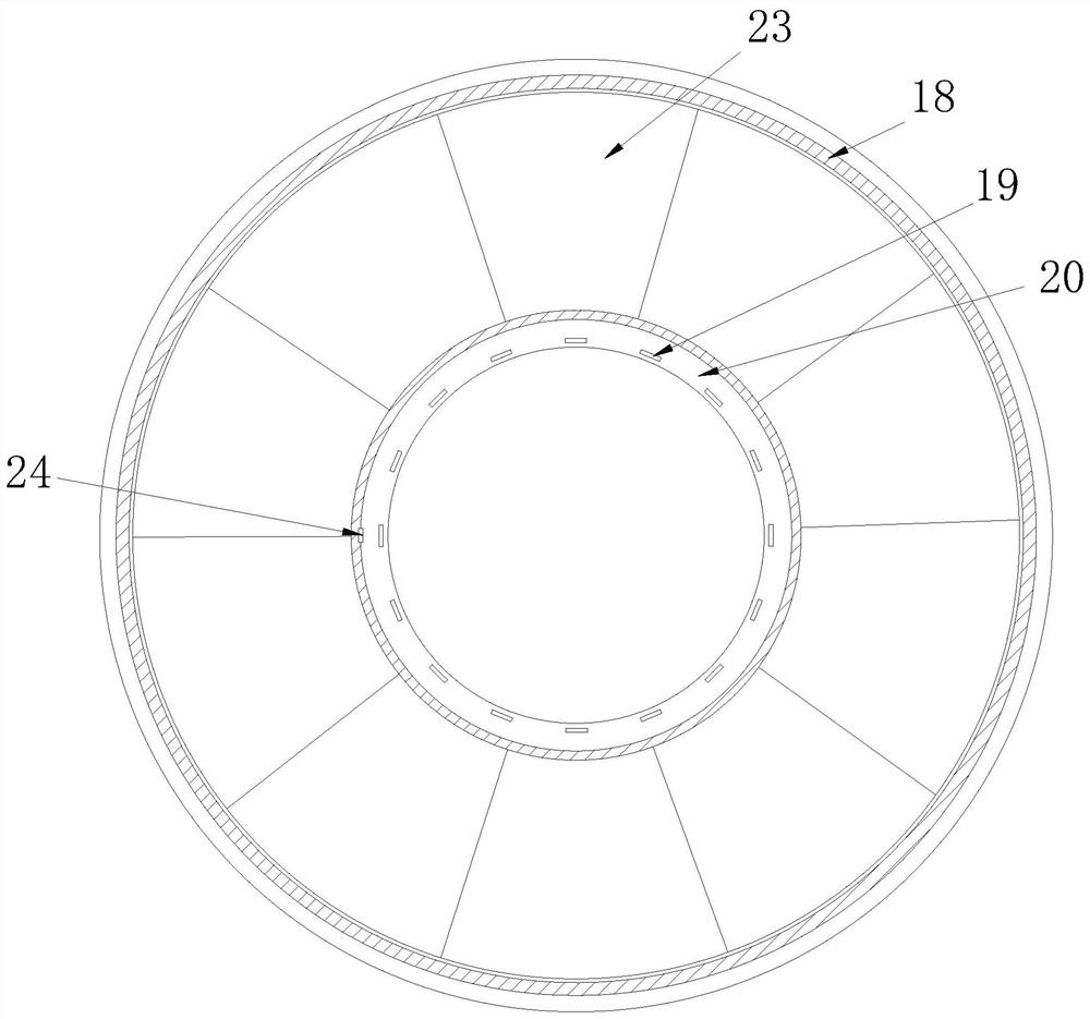
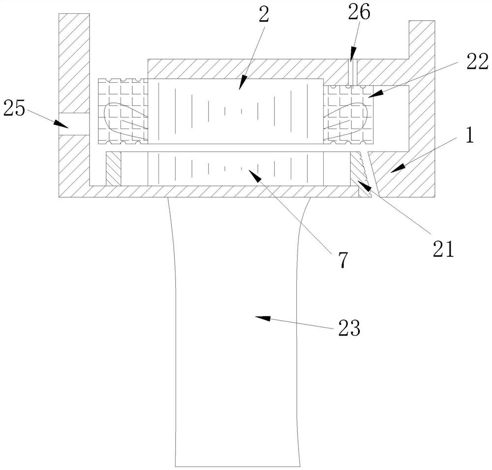
[0025] see Figure 1-3 As shown, a permanent magnet external rotor submersible pump is composed of a water inlet body 1, a stator 2, a rotor 7, an impeller 17, a water outlet body 15, an impeller casing 18 and a rotating shaft 9; the rotor 7 is sleeved on the rotating shaft through a rotor bracket 8 9, the two ends of the rotating shaft 9 are provided with a water inlet end bearing 3 and an outlet water temple bearing 10; The two sides of the water outlet bearing 10 are respectively provided with a water outlet mechanical ...


PUM


Abstract

The invention discloses a permanent magnet outer rotor submersible electric pump, which is used for solving the problem of low efficiency of a submersible electric pump unit caused by overlarge volume of a rotor and large water friction loss generated by rotation in water during rotation of the existing submersible electric pump, and comprises a water inlet body, a stator, a rotor, a water outlet body, an impeller shell and a rotating shaft. Along with the reduction of the diameter of the rotor, the water friction loss is greatly reduced, the water friction loss is in direct proportion to the quintic square of the outer circumference, and therefore, the efficiency of a unit is greatly improved. Stator windings adopts enameled round copper scattered wires, the insulation thickness is greatly reduced compared with an original water-resistant winding wire, the power density of the stator is improved, the size of the unit is reduced, and the metal consumption is reduced. An insulation paste encapsulation technology is adopted for the windings at the two ends of the stator, and the operation safety of the motor in water is guaranteed. A permanent magnet magnetic steel structure is adopted for the rotor of the motor, the performance of the motor is improved, and the power density of the motor is improved.

Description

technical field [0001] The invention relates to the technical field of submersible electric pumps, in particular to a permanent magnet outer rotor submersible electric pump. Background technique [0002] The submersible pump is a kind of water pump in which both the impeller of the pump body and the motor driving the impeller are submerged in the water; the existing submersible pump is designed to have a rotor sleeved on the outer circumference of the impeller, and when rotating, the rotor is too large to rotate in water. The water friction loss is large, so that the efficiency of the submersible electric pump unit is obviously low, which is about 10 percentage points lower than that of the traditional submersible electric pump unit; in the present invention, the rotation of the motor is set on the inner circumference of the impeller. , The water friction loss is greatly reduced. According to the formula, the water friction loss is proportional to the fifth power of the oute...

Claims


Application Information

Patent Timeline
Patent Type & Authority Applications(China)
IPC IPC(8): H02K3/28H02K3/12H02K3/38H02K3/24H02K1/28H02K1/27F04D13/08
CPCH02K3/28H02K3/12H02K3/38H02K1/2786H02K1/28H02K3/24F04D13/086
Inventor 朱庆龙金雷梁樑魏庆军张帅陈波波叶卫宁江涵
Owner HEFEI HENGDAJIANGHAI PUMP IND CO LTD
Learn More