
Limiting device used for thin-wall die casting

A technology for limit devices and die-casting parts, which is applied in the direction of workpiece clamping devices, electromechanical devices, electrical components, etc., which can solve the problems that are prone to errors, the inability to limit the center of thin-walled die-castings, and the surface treatment of thin-walled die-castings. problem, to achieve the effect of convenient surface treatment

Pending Publication Date: 2021-04-27
江苏顺源航空零部件有限公司
View PDF6 Cites 0 Cited by
  • Summary
  • Abstract
  • Description
  • Claims
  • Application Information

AI Technical Summary

Problems solved by technology

[0004] The problem to be solved by the present invention is to provide a cleaning device for special steel castings, which solves the problem that the existing limiting device cannot limit the center of thin-walled die-castings during the processing of thin-walled die-castings such as motor housings. operation, it is not convenient to process the surface of thin-walled die-castings; in the process of processing multiple thin-walled die-castings at the same time, it is necessary to accurately position the thin-walled die-castings and the processing parts, otherwise errors will easily occur in the subsequent processing technical issues

Method used


Image

  • Limiting device used for thin-wall die casting
  • Limiting device used for thin-wall die casting
  • Limiting device used for thin-wall die casting

Examples


Embodiment approach

[0039] As an embodiment of the present invention, the specific operation steps of the limiting device are as follows:

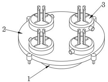
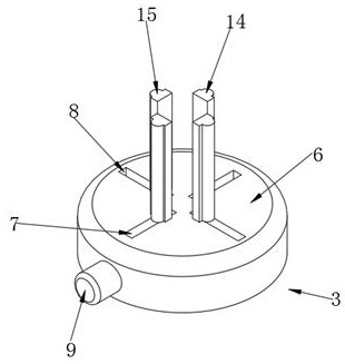
[0040]Step 1: Place the thin-walled die-casting part on the limit mechanism 3. At this time, the second servo motor 9 on the fixed seat 6 works to drive the first threaded rod 10 to rotate. At this time, the rotating worm 11 cooperates with the meshing worm gear 12 for transmission. , and then drive the second threaded rod 13 to rotate. At this time, the first sliding rod 14 and the second sliding rod 15 are respectively driven to approach or move away from the first sliding groove 7 and the second sliding groove 8 until the first sliding rod 14 and the second sliding groove 8 The second sliding rods 15 are all in contact with the inner wall of the thin-walled die-casting, so as to realize the limit of the thin-walled die-casting;

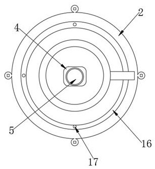
[0041] Step 2: At this time, the first servo motor 5 works, the reducer 4 adjusts the speed to drive the turntable 2 to rotate, ...


PUM


Abstract

The invention relates to a limiting device used for a thin-wall die casting. The limiting device comprises a base, a rotary table and limiting mechanisms, the rotary table is rotationally installed at the top of the base, the plurality of limiting mechanisms are installed on the top side of the rotary table at equal intervals, each limiting mechanism comprises a fixing seat, a first sliding groove and a second sliding groove are formed in the top side of each fixing seat, and the first sliding grooves are arranged perpendicular to the second sliding grooves. The thin-wall die casting is placed on the limiting mechanisms, at the moment, a second servo motor on each fixing seat works to drive a first threaded rod to rotate, at the moment, a rotating worm and a meshing turbine are in matched transmission, then a second threaded rod is driven to rotate, at the moment, a first sliding rod and a second sliding rod are driven to get close to or get away from each other simultaneously in the first sliding grooves and the second sliding grooves respectively, until the first sliding rod and the second sliding rod are both in contact with the inner wall of the thin-wall die casting, and therefore limiting of the thin-wall die casting is realized, and the thin-wall die casting is mounted in the centers of the limiting mechanisms, so that subsequent surface treatment is facilitated.

Description

technical field [0001] The invention relates to the technical field of thin-wall die-casting processing, in particular to a limiting device for thin-wall die-casting parts. Background technique [0002] Die-casting is a kind of pressure-casting part. It uses a pressure-casting mechanical die-casting machine equipped with a casting mold to pour liquid copper, zinc, aluminum or aluminum alloy into the feed port of the die-casting machine, and passes through the die-casting machine. Die casting, casting copper, zinc, aluminum parts or aluminum alloy parts of the shape and size limited by the mold, such parts are usually called die castings. [0003] During the processing of thin-walled die-casting parts such as motor casings, the existing limit device cannot perform center limit operation on thin-walled die-casting parts, which is not convenient for processing the surface of thin-walled die-casting parts; In the process of processing parts, it is necessary to accurately locate...

Claims


Application Information

Patent Timeline
IPC IPC(8): B25B11/00B08B13/00H02K15/14
CPCB25B11/00B08B13/00H02K15/14
Inventor 顾斌杰
Owner 江苏顺源航空零部件有限公司
Learn More