Unlock instant, AI-driven research and patent intelligence for your innovation.

Ultra-wideband miniaturized power divider, design method and multi-channel communication network terminal

A design method and power divider technology, applied to waveguide devices, circuits, connection devices, etc., can solve problems such as difficult in-band insertion loss, excessive frequency band loss, and difficulty in reducing the size of power dividers

Inactive Publication Date: 2021-04-27
XIDIAN UNIV
View PDF5 Cites 0 Cited by
  • Summary
  • Abstract
  • Description
  • Claims
  • Application Information

AI Technical Summary

Problems solved by technology

[0005] Through the above analysis, the existing problems and defects of the prior art are: the prior art ultra-wideband power splitter mainly adopts the method of multi-section matching, and the performance of the power splitter obtained by using this method is relatively good, the volume is too large, and Prone to excessive in-band loss
[0006] The difficulty in solving the above problems and defects is: due to the wide frequency band of the ultra-wideband power splitter, there are too many branches required, which makes it difficult to reduce the size of the power splitter, and the frequency band span of the power splitter is large, so in order to To ensure the performance of the power splitter in the full frequency range, the power splitter must have a good transition in different frequency bands. It is quite difficult for the in-band insertion loss to be linear in the ultra-wide frequency band

Method used


Image

  • Ultra-wideband miniaturized power divider, design method and multi-channel communication network terminal
  • Ultra-wideband miniaturized power divider, design method and multi-channel communication network terminal
  • Ultra-wideband miniaturized power divider, design method and multi-channel communication network terminal

Examples


Embodiment Construction

[0050] In order to make the object, technical solution and advantages of the present invention clearer, the present invention will be further described in detail below in conjunction with the examples. It should be understood that the specific embodiments described here are only used to explain the present invention, not to limit the present invention.

[0051] Aiming at the problems existing in the prior art, the present invention provides an ultra-wideband miniaturized power divider, a design method, and a multi-channel communication network terminal. The present invention will be described in detail below in conjunction with the accompanying drawings.

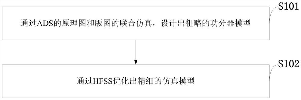
[0052] Such as figure 1 As shown, the design method of the ultra-wideband miniaturized power splitter provided by the present invention comprises the following steps:

[0053] S101: Design a rough power divider model through the co-simulation of the schematic diagram and layout of the ADS;

[0054] S102: Optimizing a fine ...


PUM

PropertyMeasurementUnit
Thicknessaaaaaaaaaa

Abstract

The invention belongs to the technical field of radio frequency circuits, and discloses an ultra-wideband miniaturized power divider, a design method and a multi-channel communication network terminal. A rough power divider model is designed through joint simulation of a schematic diagram and a layout of an ADS; and a fine simulation model is optimized through the HFSS. A rough power divider model is designed through joint simulation of a schematic diagram and a layout of the ADS, then a fine simulation model is optimized through the HFSS, and a test result of the finally designed 1G-15G ultra-wideband power divider divided into two power dividers shows that in the whole frequency band, the return loss is smaller than -15dB, the insertion loss is smaller than 2dB, and the isolation degree of two ports is smaller than -13dB. According to the invention, the waveguide is used for transition, and the planar ground of the waveguide cannot interfere with the microstrip line of the power divider twice, so reflection and loss can be greatly reduced; resistors are all welded on the surface by adopting chip resistors, and soldering tin is ensured to be less as much as possible when the resistors and joints are welded.

Description

technical field [0001] The invention belongs to the technical field of radio frequency circuits, and in particular relates to an ultra-wideband miniaturized power divider, a design method, and a multi-channel communication network terminal. Background technique [0002] At present: Ultra-wideband technology has broad application prospects in microwave systems because of its good concealment, high transmission rate, and large space capacity. Ultra-wideband technology has high requirements on the frequency band, so the fabrication of wide-band microwave radio frequency devices has become the focus of research. A power splitter is a multi-port microwave network that divides the input signal power into several outputs, and is widely used in micro-blog equipment such as multi-channel communication networks and phased array radars. The power splitter can also be used in reverse for power synthesis, so some people call it a power distribution / combiner. The Wilkinson power divider...

Claims


Application Information

Patent Timeline
IPC IPC(8): H01P11/00H01P5/16
CPCH01P5/16H01P11/00
Inventor 于丁傅云龙杨林王建勋
Owner XIDIAN UNIV