
A vibration-damping clamping tool for large thin-walled parts

A technology for large thin-walled parts and thin-walled workpieces, which is applied in the field of large-scale thin-walled parts vibration damping and clamping tooling, can solve the problems of inconvenient installation and disassembly, low positioning accuracy, and poor clamping quality, and achieves easy installation and strong adaptability. , Good vibration damping effect

Active Publication Date: 2022-04-05
HENAN AEROSPACE HYDRAULIC & PNEUMATIC TECH
View PDF15 Cites 0 Cited by
  • Summary
  • Abstract
  • Description
  • Claims
  • Application Information

AI Technical Summary

Problems solved by technology

[0003] Aiming at the technical problems of existing thin-walled fixtures such as complex structure, inconvenient installation and disassembly, low positioning accuracy, poor clamping quality, self-excited vibration and deformation, and inability to meet the clamping and use requirements of thin-walled workpieces of different sizes, the present invention A vibration damping and clamping tool for large thin-walled parts is proposed, which can not only improve the positioning and clamping quality of thin-walled workpieces, but also alleviate the self-excited vibration in the process of processing, and avoid factors such as the state of the material itself and thermal stress in the process of processing. Causes deformation of thin-walled workpieces

Method used


Image

  • A vibration-damping clamping tool for large thin-walled parts
  • A vibration-damping clamping tool for large thin-walled parts
  • A vibration-damping clamping tool for large thin-walled parts

Examples


Embodiment 1

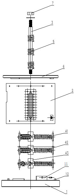
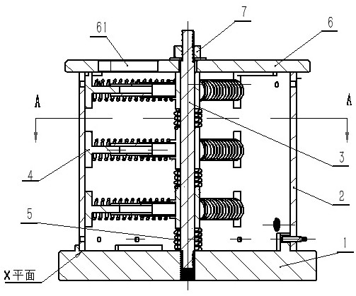
[0020] Example 1, such as figure 1 and figure 2 As shown, the present invention provides a vibration damping and clamping tool for large thin-walled parts, including a positioning substrate 1, a thin-walled workpiece 2 is arranged on the positioning substrate 1, and a pressing assembly is arranged on the upper part of the thin-walled workpiece 2, namely The thin-walled workpiece 2 is clamped between the positioning base plate 1 and the pressing assembly. The inside of the thin-walled workpiece 2 is provided with a main tie rod 3 in the axial direction, preferably the main tie rod 3 is arranged along the axis of the thin-walled workpiece 2, and the two ends of the main tie rod 3 are fixedly connected with the positioning substrate 1 and the pressing assembly respectively, so as to realize the alignment of the thin-walled workpiece 2. Axial positioning of workpiece 2. Several groups of tensioning components 4 are arranged on the main tie rod 3, and the tensioning components 4...

Embodiment 2

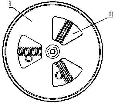
[0026] Example 2, such as image 3 As shown, a large-scale thin-walled vibration damping and clamping tool, the positioning platen 6 is provided with a through hole 61, in this embodiment, the through hole 61 is a fan-shaped structure, and along the central axis of the positioning platen 6 There are 3 evenly set. The functions of the three through holes are as follows: first, it is used to reduce the weight of the entire tooling, which is beneficial to disassembly, movement, and hoisting of large thin-walled workpieces; second, it is beneficial to cutting fluid processing Inner cavity; thirdly, it is convenient to observe the use state of the tensioning component, so as to prevent abnormal phenomena and damage to thin-walled workpieces.

[0027] Other structures are the same as in Embodiment 1.


PUM


Abstract

The present invention proposes a vibration damping clamping tool for large thin-walled parts, which is used to solve the problems of complex structure, inconvenient installation and disassembly, low positioning accuracy, poor clamping quality, self-excited vibration and Due to its own state and thermal stress in the process of processing, thin-walled workpieces are deformed, and technical problems such as the inability to meet the clamping and use requirements of thin-walled workpieces of different sizes. The invention comprises a positioning base plate, on which a thin-walled workpiece is arranged, a pressing assembly is arranged on the upper part of the thin-walled workpiece, and a main pull rod is arranged axially inside the thin-walled workpiece, and the two ends of the main pull rod are connected with the positioning base plate and the positioning base plate respectively. The pressing assembly is fixedly connected, and several groups of holding assemblies are arranged on the main pull rod, and the holding assemblies cooperate with the thin-walled workpiece. The invention can not only improve the positioning and clamping quality of the thin-walled workpiece, but also relieve the self-excited vibration in the processing process, and avoid deformation of the thin-walled workpiece due to the state of the material itself and thermal stress in the processing process.

Description

technical field [0001] The invention relates to the technical field of machining fixtures, in particular to a vibration-damping clamping tool for large thin-walled parts. Background technique [0002] Large-scale rotary thin-walled parts have been widely used in the construction machinery industry. It has the characteristics of light weight, compact structure, and material saving. Because it plays an important role in mechanical assembly, it must ensure a high degree of precision during processing. Dimensional accuracy and surface roughness. However, the large diameter and thin wall thickness of large rotary thin-walled parts lead to poor rigidity and weak strength, and are prone to deformation and vibration under the action of clamping force and cutting force. The workmanship is poor. However, the existing fixtures for thin-walled parts have a complex overall structure, are not easy to install and disassemble, have low positioning accuracy, poor clamping quality, and are ...

Claims


Application Information

Patent Timeline
Patent Type & Authority Patents(China)
IPC IPC(8): B23Q3/06
CPCB23Q3/06
Inventor 卓靳露苏征刘宝林韩华伟邵振振刘来运苑高辉葛赛孔令海
Owner HENAN AEROSPACE HYDRAULIC & PNEUMATIC TECH
Learn More