Noise reduction device for splicing warp knitting machine

A warp knitting machine and splicing technology, which is applied in warp knitting, mechanical equipment, knitting, etc., can solve the problems of unfavorable health of workers, lack of noise reduction devices, and erosion of workers, so as to reduce the harm of noise to the human body , Convenient shock absorption and noise reduction, and the effect of protecting your health

Active Publication Date: 2022-06-03
CHANGDE TEXTILE MACHINERY
View PDF0 Cites 0 Cited by
  • Summary
  • Abstract
  • Description
  • Claims
  • Application Information

AI Technical Summary

Problems solved by technology

[0002] The warp knitting machine uses one or several groups of yarns arranged in parallel to form a loop on all the working needles of the warp feeding machine at the same time to form a knitted fabric. This method is called warp knitting, and the fabric is called warp knitted fabric. The machine that completes this kind of warp knitting is called a warp knitting machine. The warp knitting machine will vibrate when it is in use, which will generate a lot of noise. However, the current warp knitting machine does not have a suitable noise reduction device, which causes the staff to be exposed to noise for a long time The erosion of the eardrum will cause damage to the staff, which is not conducive to the health of the staff. In view of this, we propose a noise reduction device for splicing warp knitting machines

Method used


Image

  • Noise reduction device for splicing warp knitting machine
  • Noise reduction device for splicing warp knitting machine
  • Noise reduction device for splicing warp knitting machine

Examples


Embodiment 1

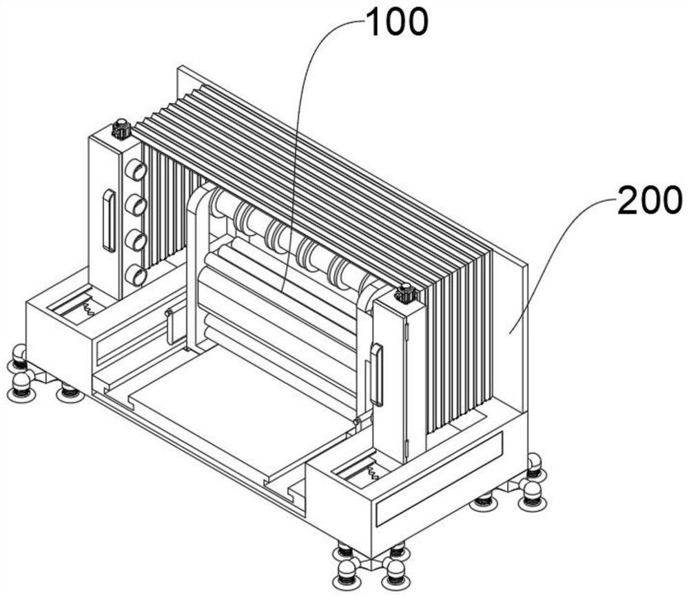
[0052] The support plate 210, the cross section of the support plate 210 is in a "U" shape, and the warp knitting machine body 100 is located in the center of the support plate 210

[0053] When the support plate 210 in the present invention is used specifically, the warp knitting machine body 100 is located inside the support plate 210, so that the support

[0059] It should be noted that the inner surface of the power plate 212 near the top is provided with a limit frame 2121, and the rack 2122 is located at the limit

[0062] Specifically, the clamping plate 214 is in the shape of a "cuboid", the clamping plate 214 is made of elastic rubber, and the outer wall of the clamping plate 214 is

[0065] Wherein, the inner cavity of the adjustment column 233 is rotated and provided with a transmission screw 234, and the end of the transmission screw 234 rotates and extends out of the adjustment column

[0066] Specifically, the outer wall of the cleaning frame 2351 is provided with a c...


PUM


Abstract

The invention relates to a noise reduction device, in particular to a noise reduction device for splicing warp knitting machines. It includes the warp knitting machine body and the protection and noise reduction mechanism on the outside of the warp knitting machine body. Two symmetrical moving blocks are arranged at the bottom of the warp knitting machine body. The protection and noise reduction mechanism includes at least: a support plate, a buffer plate and a sound insulation device. The acoustic device includes a connecting plate, which is fixedly connected to the top edge of the supporting plate, and the inner surface of the connecting plate is provided with a folding cover, which is in the shape of an "organ". A symmetrical adjustment column, the bottom of the adjustment column is provided with a slider, the slider is slid inside the chute, the bottom of the slider is rotated with a gear plate, the outer wall of the gear plate is meshed with the outer wall of the rack, and the end of the gear plate is fixedly connected with a rotating motor The output shaft, the present invention is convenient to reduce the noise of the warp knitting machine body, so that the noise of the warp knitting machine body is cut off when it is working, which is beneficial to protect the health of the staff.

Description

A noise reduction device for a spliced ​​warp knitting machine technical field [0001] The present invention relates to a noise reduction device, in particular, to a noise reduction device for a spliced ​​warp knitting machine. Background technique [0002] The warp knitting machine uses one or several groups of yarns arranged in parallel, on all the working needles of the warp feeding machine, simultaneously forming The knitted fabric is formed by looping, this method is called warp knitting, the fabric is called warp knitting, and the machine that completes this warp knitting is called warp knitting The warp knitting machine will vibrate when it is in use, resulting in a large noise, but the current warp knitting machine does not have suitable noise reduction The device will cause the staff to be eroded by noise for a long time, causing damage to the eardrum, which is not conducive to the health of the staff. In view of this, we propose a noise reduction device for sp...

Claims


Application Information

Patent Timeline
Patent Type & Authority Patents(China)
IPC IPC(8): D04B27/00D04B35/32F16F15/067
CPCD04B27/00D04B35/32F16F15/067Y02P70/62
Inventor 陈鹏陈海军严中华
Owner CHANGDE TEXTILE MACHINERY
Why Eureka
Try Eureka