Anti-collision assembly type steel bridge

A prefabricated, anti-collision technology, used in bridges, bridge parts, bridge construction, etc., can solve the problems of slippery pedal surface, reduced performance, poor braking effect, etc., to improve safety performance and improve braking effect. , the effect of avoiding casualties

Inactive Publication Date: 2021-04-30
张旭亮
View PDF0 Cites 3 Cited by
  • Summary
  • Abstract
  • Description
  • Claims
  • Application Information

AI Technical Summary

Problems solved by technology

[0005] Aiming at the deficiencies of the prior art, the present invention provides an anti-collision assembled steel bridge, which solves the problem that the structure of the existing assembled steel bridge is too simple, and the guardrail only plays a simple protective role, and has no anti-collision structure. The collision function makes the main body of the bridge and the vehicles seriously damaged, and there is a great potential safety hazard. Especially in the rainy season, the surface of the pedal is wet and slippery, the friction is small, the braking effect is poor, and the vehicle is easy to rush out of the guardrail, causing more serious accidents. , reducing performance issues using

Method used


Image

  • Anti-collision assembly type steel bridge
  • Anti-collision assembly type steel bridge
  • Anti-collision assembly type steel bridge

Examples


Embodiment example 1

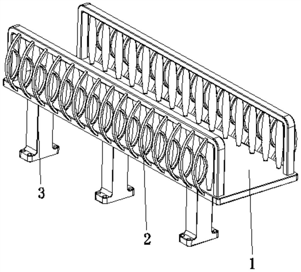
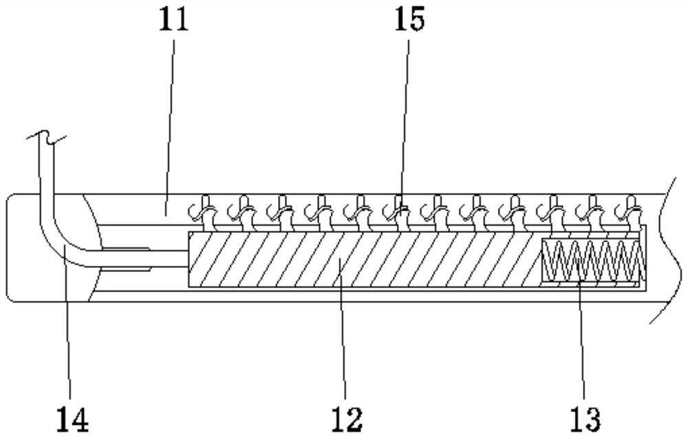
[0032] see Figure 1-7, the present invention provides a technical solution: an anti-collision assembled steel bridge, including a pedal device 1, a guardrail device 2, a support column 3, the guardrail device 2 is fixed on the two sides corresponding to the top of the pedal device 1, and the support column 3 Fixed on the central position of the bottom of the pedal device 1, the pedal device 1 is provided with a pedal body 11, a sliding plate 12, a return spring 13, a right-angle connecting rod 14, a friction device 15, the sliding plate 12 is slidably connected to the inside of the pedal body 11, and the return spring 13 is fixed between the two sides corresponding to the end of the sliding plate 12 and the inside of the pedal body 11. The right-angled connecting rod 14 is fixed on the end of the sliding plate 12 away from the return spring 13. The top of the right-angled connecting rod 14 is aligned with the surface of the guardrail device 2. The side is fixedly connected, a...

Embodiment example 2

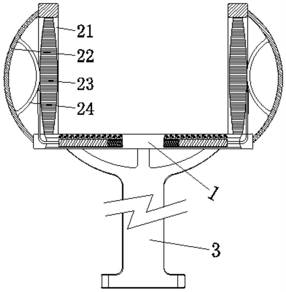
[0036] Guardrail device 2 is provided with U-shaped fixed mount 21, arc-shaped support 22, fence device 23, buffer member 24, and the opening of U-shaped fixed mount 21 is downward and is fixed on the top of pedal device 1, and arc-shaped support 22 is fixed on U Between the top of the surface of the U-shaped fixture 21 and the two sides corresponding to the surface of the pedal device 1, the barrier device 23 is fixed between the top of the inner wall of the U-shaped fixture 21 and the two sides corresponding to the top of the pedal device 1, and the buffer member 24 is fixed on Between the two sides corresponding to the surface of the barrier device 23 and the inner wall of the arc-shaped support 22, when being hit, the barrier device 23 is elastically deformed to provide a buffer distance and provide initial protection. At the same time, the arc-shaped support 22 can make the guardrail device 2 more stable , and provide support for the buffer member 24 at the same time, whic...


PUM


Abstract

The invention discloses an anti-collision assembly type steel bridge which comprises a pedal device, guardrail devices and supporting columns, the guardrail devices are fixed to the two corresponding sides of the top of the pedal device, a sliding plate is connected into a pedal body in a sliding mode, and a reset spring is fixed between the end of the sliding plate and the two corresponding sides of the interior of the pedal body. And the top end of the right-angle connecting rod is fixedly connected with one side of the surface of the guardrail device, the friction device is arranged between the top of the sliding plate and the two corresponding sides of the interior of the pedal body, and the friction device is close to the surface of the pedal body. The invention relates to the technical field of bridges. According to the anti-collision assembly type rigid bridge, the purposes of collision prevention and timely friction increase are achieved, buffering and impact force reduction are conducted in time, protection of the bridge and a vehicle is facilitated, the friction force is increased in time, the vehicle braking effect is improved, the situation that the vehicle rushes out of a guardrail is reduced, safety and reliability are achieved, potential safety hazards are reduced, and the using performance is improved.

Description

technical field [0001] The invention relates to the technical field of bridges, in particular to an anti-collision assembled steel bridge. Background technique [0002] The prefabricated bridge is to divide the tall pier into several components along the vertical direction, according to a certain modulus, and horizontally, pour it on the prefabricated site around the bridge site, transport it to the site by vehicle and ship, lift and assemble it, and then splice the bridge deck on the pier on the stage to achieve the purpose of rapid construction. Therefore, the fully prefabricated bridge structure is an effective means to speed up construction, reduce on-site pollution, and achieve low-carbon construction. Under the guidance of national policies and technological development, bridge prefabricated structures have also been more and more widely used in various projects. The prefabricated bridge has reliable quality, intelligent steel bar processing, factory-like component p...

Claims


Application Information

Patent Timeline
Patent Type & Authority Applications(China)
IPC IPC(8): E01D1/00E01D19/10
CPCE01D1/00E01D19/10E01D19/103
Inventor 周冠连
Owner 张旭亮
Why Eureka
Try Eureka