U-shaped irrigation ditch sludge removal equipment for irrigation and water conservancy

A farmland water and U-shaped technology, which is applied in the direction of mechanically driven excavators/dredgers, earth movers/shovelers, construction, etc., can solve the problem of affecting irrigation ditches to irrigate farmland, the range of silt treatment is small, and silt is inside To reduce the burden of cleaning and maintenance, improve the removal range, and improve safety

Inactive Publication Date: 2021-04-30
王玉菲
View PDF8 Cites 0 Cited by
  • Summary
  • Abstract
  • Description
  • Claims
  • Application Information

AI Technical Summary

Problems solved by technology

[0002] In order to ensure that the farmland has water supply, it is necessary to build irrigation ditches. Most of the existing irrigation ditches are buildings with a U-shaped vertical section formed by pouring cement. When the irrigation ditches are in use, there will be silt inside them. After a long time, It will affect the irrigation ditches to irrigate the farmland, so it is necessary to carry out silt operation on the irrigation ditches regularly
[0003] Most of the existing desilting work for U-shaped irrigation ditches uses personnel to use shovels to shovel out the silt in the ditch or extract it through external equipment. danger, and the latter can’t extract the silt adhering to the inner wall of the irrigation ditch well. At the same time, both of these two methods have a small treatment range for the silt in the irrigation ditch, and the effect of removing the silt is poor. Therefore, we propose a U-shaped irrigation ditch desilting equipment for farmland water utilization

Method used


Image

  • U-shaped irrigation ditch sludge removal equipment for irrigation and water conservancy
  • U-shaped irrigation ditch sludge removal equipment for irrigation and water conservancy
  • U-shaped irrigation ditch sludge removal equipment for irrigation and water conservancy

Examples


Embodiment Construction

[0024] The following will clearly and completely describe the technical solutions in the embodiments of the present invention with reference to the accompanying drawings in the embodiments of the present invention. Obviously, the described embodiments are only some, not all, embodiments of the present invention. Based on the embodiments of the present invention, all other embodiments obtained by persons of ordinary skill in the art without making creative efforts belong to the protection scope of the present invention.

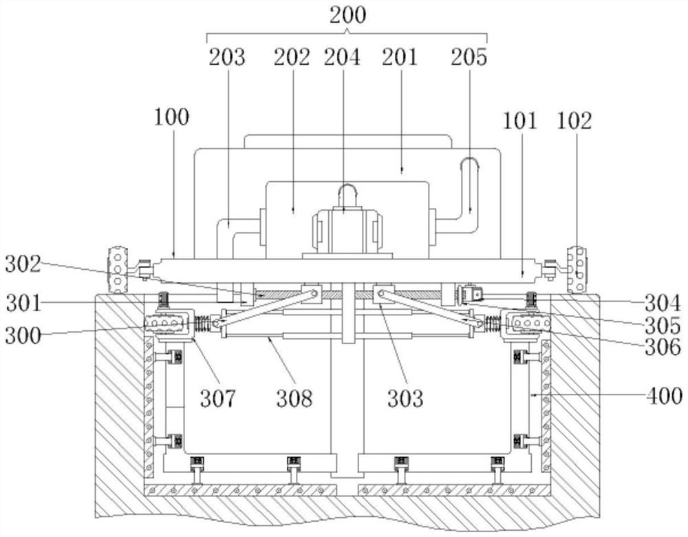
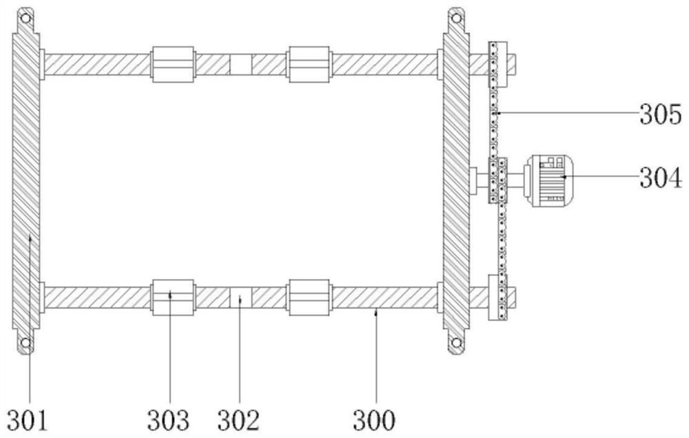
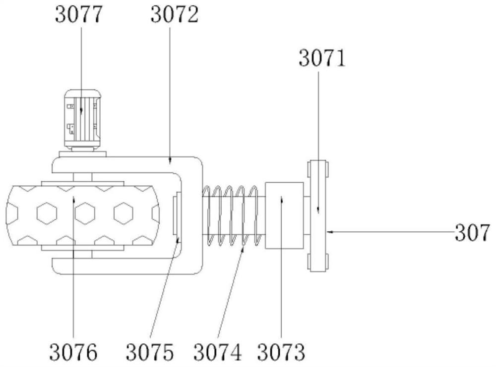
[0025] see Figure 1-4 , the present invention provides a U-shaped irrigation ditch desilting equipment for farmland water utilization, including a receiving assembly 100, including a receiving plate 101, and follower wheels 102 are arranged on the outer walls of the receiving plate 101, and the follower wheels 102 on both sides are respectively mounted. It is connected to both sides of the top of the irrigation ditch to play a supporting role; the sludge trea...


PUM


Abstract

The invention discloses U-shaped irrigation ditch sludge removal equipment for irrigation and water conservancy in the technical field of irrigation and water conservancy. The U-shaped irrigation ditch sludge removal equipment comprises a bearing assembly, a sludge treatment assembly and an adjusting assembly, wherein the bearing assembly comprises a bearing plate, and follow-up wheels are arranged on the outer wall of the periphery of the bearing plate; the sludge treatment assembly comprises a collection box fixed to the rear side of the top of the bearing plate, and a sludge extraction device is connected with a sludge-water separation device through a pipeline; and the adjusting assembly is arranged at the bottom of the bearing plate. The U-shaped irrigation ditch sludge removal equipment is provided with the adjusting assembly and walking wheel assemblies, driving motors of the walking wheel assemblies drive walking wheels to rotate, and then through friction force, the equipment can drive scraping assemblies at the bottom to move in an irrigation ditch, so that on one hand, the scraping assemblies can conveniently scrape sludge adhering to the inner wall of the irrigation ditch in the moving process, and on the other hand, the sludge removal range in the irrigation ditch is widened, the sludge removal quality and efficiency are improved, and meanwhile, the labor intensity of workers is greatly reduced, and the use safety is improved.

Description

technical field [0001] The invention relates to the technical field of farmland water utilization, in particular to a U-shaped irrigation ditch desilting device for farmland water utilization. Background technique [0002] In order to ensure that the farmland has water supply, it is necessary to build irrigation ditches. Most of the existing irrigation ditches are buildings with a U-shaped vertical section formed by pouring cement. When the irrigation ditches are in use, there will be silt inside them. After a long time, It will affect the irrigation ditches to irrigate the farmland, so it is necessary to carry out the silt operation on the irrigation ditches regularly. [0003] Most of the existing desilting work for U-shaped irrigation ditches is carried out by the user using a shovel to shovel out the silt in the ditch or extracting it through external equipment. danger, and the latter can’t extract the silt adhering to the inner wall of the irrigation ditch well. At the...

Claims


Application Information

Patent Timeline
Patent Type & Authority Applications(China)
IPC IPC(8): E02F3/28E02F5/28
CPCE02F3/28E02F5/28
Inventor 王玉菲
Owner 王玉菲
Why Eureka
Try Eureka