
Energy-gathering joint-cutting pipe

An energy-gathering tube and energy-gathering technology, which is applied in the field of blasting, can solve problems such as difficult control of harmful effects, loss of life and property, over-excavation and under-excavation of rocks, etc., so as to reduce the unit consumption of explosives, uniform direction of energy-gathering slits, and harmless The effect of reducing the effect

Pending Publication Date: 2021-04-30
ANHUI UNIV OF SCI & TECH
View PDF7 Cites 0 Cited by
  • Summary
  • Abstract
  • Description
  • Claims
  • Application Information

AI Technical Summary

Problems solved by technology

[0002] In engineering projects such as mine mining and tunnel forming, blasting operations are required, but general blasting operations have fewer holes and more charges, resulting in a series of engineering problems, such as rock over-excavation and under-excavation, poor light blasting effect, Excessive blasting vibration, etc.
Especially when blasting operations are carried out in complex environments, harmful effects such as blasting vibration, blasting flying stones, and noise are difficult to control, which can easily cause loss of life and property

Method used


Image

  • Energy-gathering joint-cutting pipe
  • Energy-gathering joint-cutting pipe
  • Energy-gathering joint-cutting pipe

Examples


Embodiment Construction

[0020] The technical solutions in the embodiments of the present invention will be clearly and completely described below in conjunction with the accompanying drawings in the embodiments of the present invention. It should be understood that the specific embodiments described here are only used to explain the present invention and are not intended to limit the present invention. .

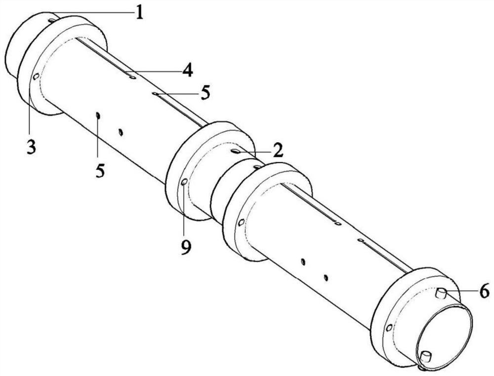
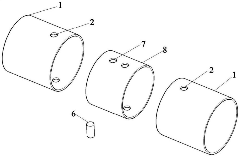
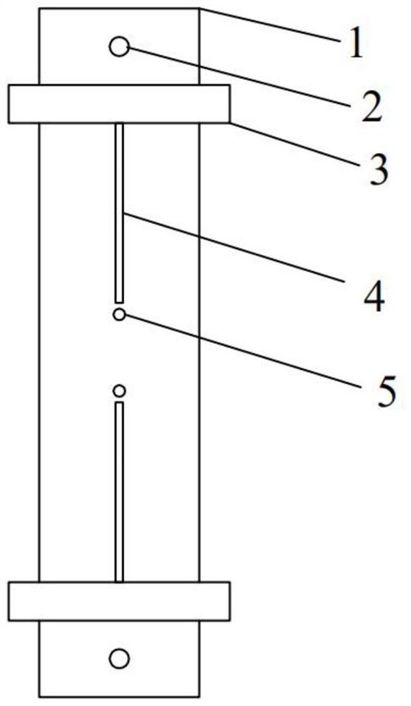
[0021] refer to Figure 1-Figure 5 As shown, an energy-gathering slit pipe device includes a pipe body 1, a first sleeve fixing hole 2, a centering foam 3, an energy-gathering slit 4, an air interval fixing hole 5, a fixing screw 6, and a second sleeve Fixing hole 7, sleeve 8, detonator line hole 9; the first sleeve fixing hole 2 is located at both ends of the tube body 1, the second sleeve fixing hole 7 is located at both ends of the sleeve 8, and the energy-gathering slit 4 is located at the tube body 1 Radial on both sides, and symmetrical to the central axis of the energy-collecting tube.

[...


PUM


Abstract

The invention relates to an energy-gathering joint-cutting pipe. The energy-gathering joint-cutting pipe comprises a pipe body, a first sleeve fixing hole, centering foam, energy-gathering joint-cuttings, air interval fixing holes, fixing screws, a second sleeve fixing hole, a sleeve and a detonator wire hole, wherein the energy-gathering joint-cuttings are located on the two radial sides of energy-gathering pipes and are symmetrical about the central axes of the energy-gathering pipes; the sleeve is a connecting piece used for connecting the two energy-gathering pipes and needs to be matched with the fixing screws for use; the sleeve fixing holes are located in the two ends of the pipe bodies of the energy-gathering pipes and the sleeve; and the centering foam is connected with the pipe bodies of the energy-gathering pipes in an adhesive mode, and the energy-gathering pipes are fixed to the central positions of blast holes. The steel energy-gathering pipes improve the constraint effect on explosives, so that the energy-gathering effect is more remarkable; and non-coupling explosive charging and radial interval explosive charging are adopted in the blast holes, the centering foam is used for guaranteeing that the circle centers of the energy-gathering pipes coincide with the circle centers of the blast holes, and the directions of the energy-gathering joint-cuttings are consistent with the pre-splitting direction, so that the unit consumption of the explosives is greatly reduced, blasting vibration is effectively controlled, and meanwhile, the construction cost is reduced.

Description

Technical field: [0001] The invention relates to the field of blasting, in particular to an energy-gathering slit pipe. Background technique: [0002] In engineering projects such as mine mining and tunnel forming, blasting operations are required, but general blasting operations have fewer holes and more charges, resulting in a series of engineering problems, such as rock over-excavation and under-excavation, poor light blasting effect, Excessive blasting vibration, etc. Especially when blasting operations are carried out in complex environments, harmful effects such as blasting vibration, blasting flying rocks, and noise are difficult to control, which can easily cause loss of life and property. Therefore, it is an urgent problem to be solved to control the harmful effects such as blasting vibration while ensuring the blasting effect. Invention content: [0003] The object of the present invention is to provide an energy-gathering slit pipe, which aims to ensure the bl...

Claims


Application Information

Patent Timeline
IPC IPC(8): F42B3/22F42B3/02F42B3/08F42D3/04
CPCF42B3/22F42B3/02F42B3/08F42D3/04
Inventor 宋凡平薛克军胡坤伦韩体飞李毅
Owner ANHUI UNIV OF SCI & TECH
Learn More