Blade complex environment test system and test method based on fiber grating sensor

A fiber grating and complex environment technology, applied in the direction of aircraft component testing, instruments, measuring devices, etc., can solve the problems of large footprint, high maintenance cost, etc., achieve fast processing speed, good accuracy, and overcome cross-sensitivity effects Effect

Active Publication Date: 2021-04-30
NANJING UNIV OF AERONAUTICS & ASTRONAUTICS
View PDF18 Cites 0 Cited by
  • Summary
  • Abstract
  • Description
  • Claims
  • Application Information

AI Technical Summary

Problems solved by technology

[0003] However, this type of experimental device can only complete a single control variable experiment, and the experimental device occupies a large area and has high maintenance costs

Method used


Image

  • Blade complex environment test system and test method based on fiber grating sensor
  • Blade complex environment test system and test method based on fiber grating sensor
  • Blade complex environment test system and test method based on fiber grating sensor

Examples


Embodiment 1

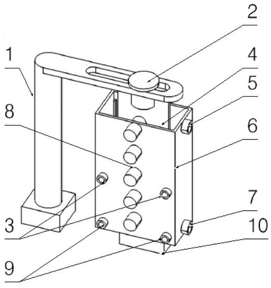
[0037] The present invention is a blade complex environment testing system based on a fiber grating sensor. The system structure includes a water tank testing device and an optical measuring device. The water tank testing device includes a blade to be tested. The generating device is used to simulate the strain of the blade at different working temperatures and when the temperature changes suddenly; the optical measuring device includes a broadband light source transmitter, a fiber coupler, and a fiber grating wavelength demodulator, which are used to generate the samples required for testing light source.

[0038] Further, the water tank testing device includes a fixed test bench, a blade fixing clip, an acrylic water tank, and a water tank fixing clip;

[0039] The fixed test bench is provided with a blade fixing clip, and the blade fixing clip hangs the blade to be tested on the fixed test bench; the blade fixing frame can move with multiple degrees of freedom and can also ...

Embodiment 2

[0051] The present application also mentions the blade complex environment test method of the above-mentioned system, and the test method includes the following steps:

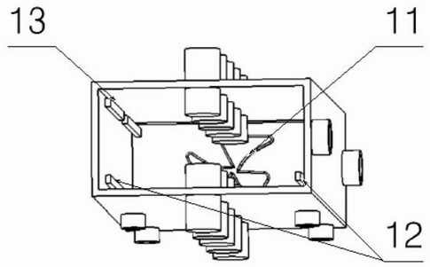
[0052] S1, before the experiment, paste the FBG sensor on the surface of the blade as required, and paste the sensor protective cover on the blade to cover the FBG sensor to prevent the sensor from being affected by external factors;

[0053] S2, connect the FBG sensor to the fiber coupler, and connect the fiber coupler to the broadband light source transmitter and the fiber grating wavelength demodulator respectively;

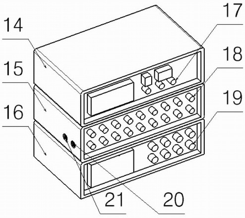
[0054] S3, connect the relevant pipelines of the water tank, the inlet of the liquid nitrogen cooling device and the outlet of the liquid nitrogen cooling device; the water outlet of the water tank and the water inlet of the water tank are respectively connected;

[0055] S4, connect related equipment, connect the temperature monitoring device with an external display, and install it on figur...


PUM


Abstract

The invention discloses a blade complex environment test system and test method based on a fiber bragg grating sensor. Through simple devices such as a fixed experiment table, an acrylic water tank, a pressure sensor, a vortex generator, a heating device, a liquid nitrogen cooling device, a temperature monitoring device, an FBG (FIBER BRAGG GRATING) a fiber bragg grating sensor, a sensor protection cover, a broadband light source emitter, a fiber coupler and a fiber bragg grating wavelength demodulator, the system and the method realize functions of controlling environment temperature, controlling a blade flow field, controlling blade centrifugal force and the like, simulate a working scene of the blade under a complex environment condition, and measure the response characteristics of the sensor under the dynamic load of a complex environment. The device has advantages of being simple in structure, low in cost, convenient to operate, high in feasibility and multiple in operable variables; and the device is high in measurement precision, good in accuracy and sensitive in reaction, and can effectively reflect the characteristics of the paddle during working. The invention is of great significance to the research of helicopters.

Description

technical field [0001] The invention relates to the intersection fields of instrumentation and science and helicopters, in particular to a blade complex environment test system based on a fiber grating sensor. Background technique [0002] The problem of dynamic load testing of helicopter blades in complex environments has always been an intractable problem that has plagued scientists in the related fields of helicopters. To solve this problem, a complex environment test system for blades based on fiber grating sensors was invented. There are many test devices in the helicopter blade test experiment, such as wind tunnel test device, vibration test device and rotary table, etc. [0003] However, this type of experimental device can only complete a single control variable experiment, and the experimental device occupies a large area and has high maintenance costs. Contents of the invention [0004] In view of the deficiencies of the above-mentioned prior art, the purpose of...

Claims


Application Information

Patent Timeline
Patent Type & Authority Applications(China)
IPC IPC(8): G01B11/16B64F5/60
CPCG01B11/165B64F5/60
Inventor 王潇詹祺李博夏品奇
Owner NANJING UNIV OF AERONAUTICS & ASTRONAUTICS
Why Eureka
Try Eureka