
Bipolar all-solid-state LTD square wave pulse generation circuit

A square wave pulse and generating circuit technology, applied in the direction of electric pulse generator circuit, energy storage element generating pulse, electrical components, etc., can solve the problem of slow pulse front, limited nanosecond and microsecond pulse square wave circuit integrated design , affecting the quality of the pulse square wave waveform, etc., to achieve the effect of improving the adjustment range, meeting the parameter requirements, and reducing the reverse voltage overshoot

Active Publication Date: 2021-04-30
XI AN JIAOTONG UNIV
View PDF5 Cites 5 Cited by
  • Summary
  • Abstract
  • Description
  • Claims
  • Application Information

AI Technical Summary

Problems solved by technology

[0004] At present, in the research on multi-parameter adjustable square wave pulse circuits at home and abroad, the realization of microsecond-level pulse width adjustment mainly adopts the Marx circuit technology scheme, the output pulse front is relatively slow, and the adjustment within the range of 100ns-1000ns mostly adopts LTD technology solution, and because the LTD circuit outputs a high-amplitude, wide-pulse-width pulse square wave voltage, a large reverse overshoot will be generated on the falling edge of the square wave at the moment of the semiconductor device being turned off, which will affect the waveform of the pulse square wave Therefore, the integrated design of nanosecond and microsecond pulse square wave circuits is limited. Currently, bipolar square wave pulse circuits that can continuously adjust the pulse width in the range of 0.1 μs to 10 μs cannot be effectively implemented.

Method used


Image

  • Bipolar all-solid-state LTD square wave pulse generation circuit
  • Bipolar all-solid-state LTD square wave pulse generation circuit
  • Bipolar all-solid-state LTD square wave pulse generation circuit

Examples


Embodiment Construction

[0025] The present invention is described in further detail below in conjunction with accompanying drawing:

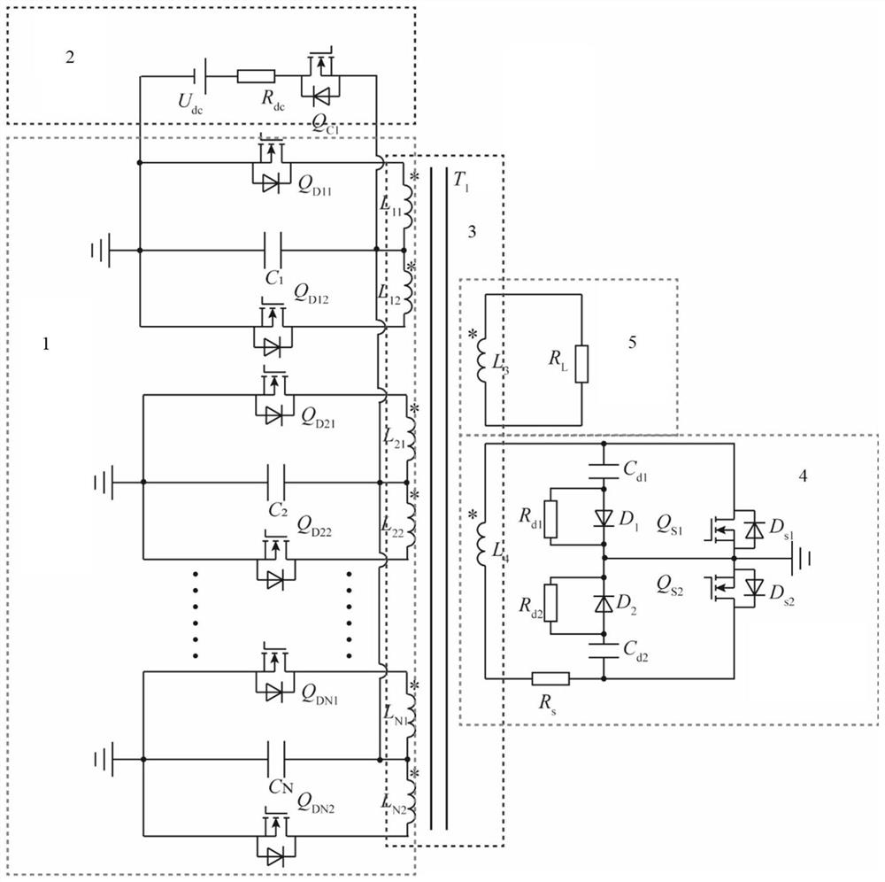
[0026] Such as figure 1 As shown, a bipolar all-solid-state LTD square wave pulse generating circuit, including LTD circuit module, pulse transformer and load resistor R L , The LTD circuit module includes a charging circuit, a bipolar push-pull discharge circuit, a load circuit and a freewheeling circuit, the output of the charging circuit is connected to the input of the bipolar push-pull discharge circuit, and the output of the bipolar push-pull discharge circuit The terminal is connected to the primary winding of the pulse transformer, the load circuit, the freewheeling circuit and the load resistance R L Both are connected to the secondary winding of the pulse transformer.

[0027] Specifically, the LTD circuit module includes N parallel bipolar push-pull discharge circuits, and the N parallel bipolar push-pull discharge circuits are connected to the same chargi...


PUM

PropertyMeasurementUnit
Resistanceaaaaaaaaaa

Abstract

The invention discloses a bipolar all-solid-state LTD square wave pulse generation circuit, which adopts an LTD circuit module, a pulse transformer and a load resistor RL, the LTD circuit module comprises a charging loop, a bipolar push-pull discharge loop, a load loop and a follow current loop, and the output end of the charging loop is connected with the input end of the bipolar push-pull discharge loop, the output end of the bipolar push-pull discharge loop is connected with a primary winding of the pulse transformer, the load loop, the follow current loop and the load resistor RL are all connected to a secondary winding of the pulse transformer, it is guaranteed that in a high-amplitude wide-pulse-width output mode, large overshoot cannot occur to the rear edge of a square wave, and bipolar high-voltage square wave pulses are output on a load. additional circuit is not needed for magnetic core reset, the pulse width of the output square wave can be continuously adjusted within the range from nanosecond to microsecond, the adjusting range of output parameters of the LTD circuit is greatly widened, and the parameter requirement of the tumor tissue irreversible electroporation ablation technology for a square wave pulse power supply can be met.

Description

technical field [0001] The invention relates to a square wave pulse generating circuit, in particular to a bipolar all-solid-state LTD square wave pulse generating circuit. Background technique [0002] Pulsed Power Technology (PPT) is an electrophysical technology that stores energy at low power and then releases it to a specific load at high power. The multi-parameter adjustable square wave pulse power supply based on pulsed power technology is used in tumor Tissue irreversible electroporation ablation has a very wide range of applications. [0003] The irreversible electroporation ablation technology of tumor tissue has the following requirements for the output parameters of the nanosecond square wave pulse power supply: the output voltage is adjustable from 0-6kV, the pulse width is adjustable from 0.1-10μs, the leading edge of the pulse is <30ns, and the polarity is bipolar. To realize the adjustment of multiple output parameters, fully controlled semiconductor devi...

Claims


Application Information

Patent Timeline
IPC IPC(8): H02M9/00H02M9/04H03K3/02H03K3/57A61B18/12A61B18/14
CPCH02M11/00H03K3/02H03K3/57A61B18/12A61B18/14Y02B70/10
Inventor 丁卫东申赛康李兰茜闫家启孙国祥邓子琛袁琪尚天一
Owner XI AN JIAOTONG UNIV
Learn More